Instrumentation serves as the “nervous system” of industrial automation, while cables and wires act as the “blood vessels” that transmit signals and energy. Proper selection and installation of cables directly affect the stability, accuracy, and reliability of measurement systems. This document introduces four commonly used types of instrumentation cables and provides engineering recommendations.
2. Instrumentation Cables
Purpose: Transmission of measurement signals and low-power supply. Widely used in PLC, DCS, sensors, and actuators.
Control System Cables
Application: Signal transmission for measurement and control loops.
Features: Shielded structures to minimize electromagnetic interference (EMI).
Power Supply Cables
Application: Supplying power to field instruments and auxiliary equipment.
Key Points: Must consider current-carrying capacity, voltage rating, and installation conditions.
Special Cables
Application: Harsh conditions (high temperature, oil resistance, chemical resistance).
Example: High-temperature cables used for furnace temperature monitoring.
Engineering Tips:
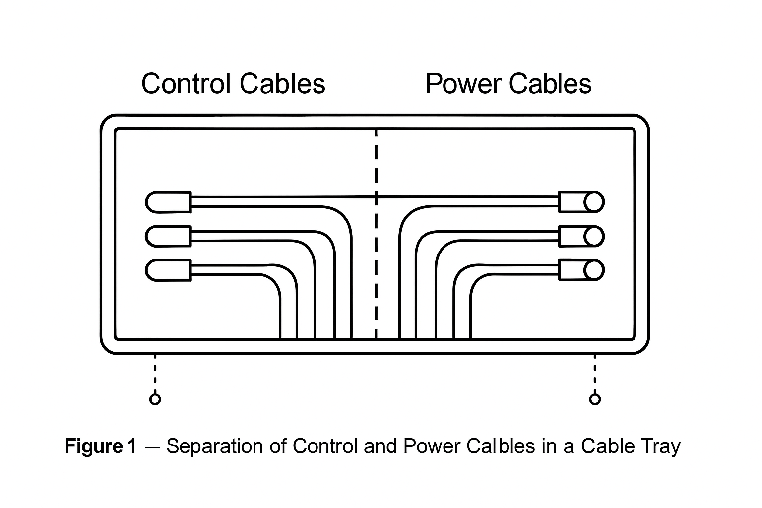
Place control and power cables in separate trays or layers to prevent crosstalk.
Use shielded control cables near variable frequency drives (VFDs) or other EMI sources.
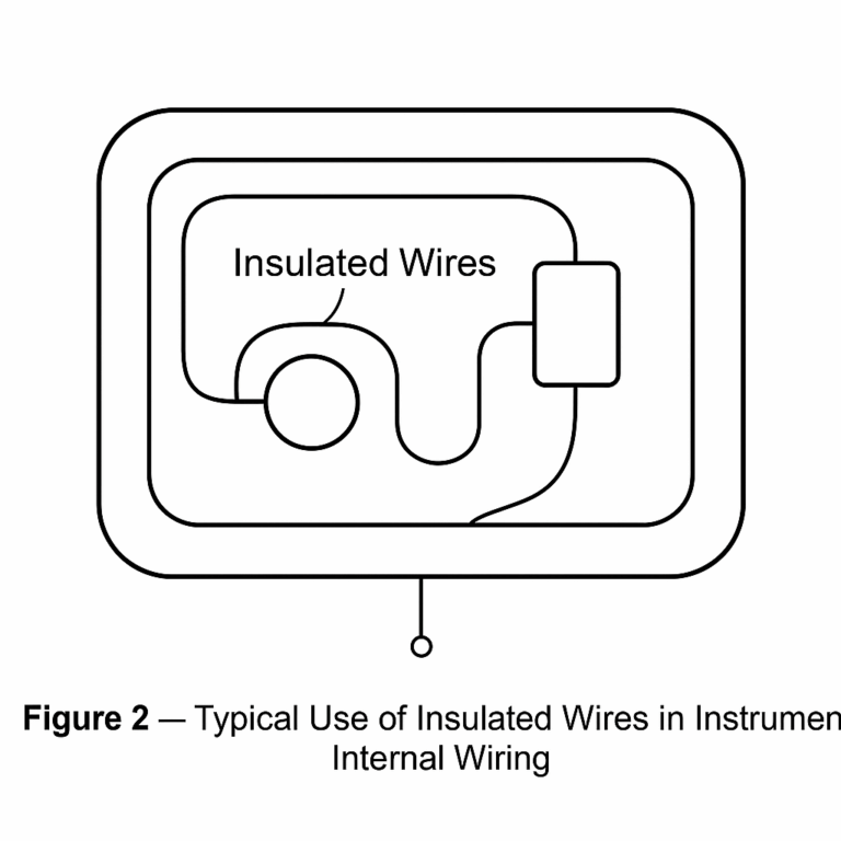
3. Insulated Wires
Purpose: Short-distance signal or internal wiring inside instruments.
Features
Simple structure, usually single-core or multi-core.
Insulation materials (PVC, PE) provide good electrical insulation.
Applications
Internal connections between instrument components.
Short control or signal wiring between terminals.
Engineering Tips: Not suitable for long-distance transmission or high-interference environments.
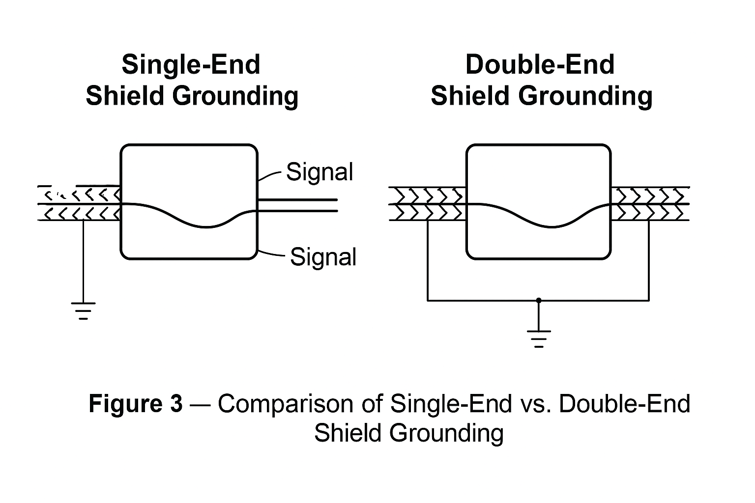
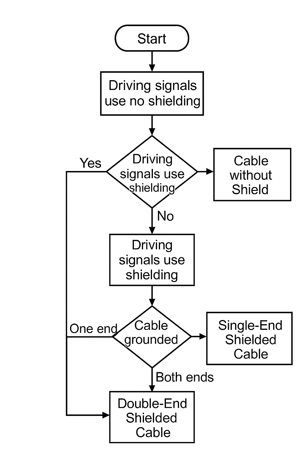
4. Shielded Wires and Cables
Purpose: Prevent interference from motors, VFDs, relays, and other high-noise equipment.
Features
Shielding layer (braided copper, aluminum foil, etc.) blocks external EMI and prevents signal leakage.
Must be correctly grounded to create a Faraday cage effect.
Applications
Strongly recommended for analog signal transmission (temperature, pressure, flow).
In harsh environments, use double-layer shielding.
Engineering Tips:
Shield grounding should typically be single-ended to avoid ground loops.
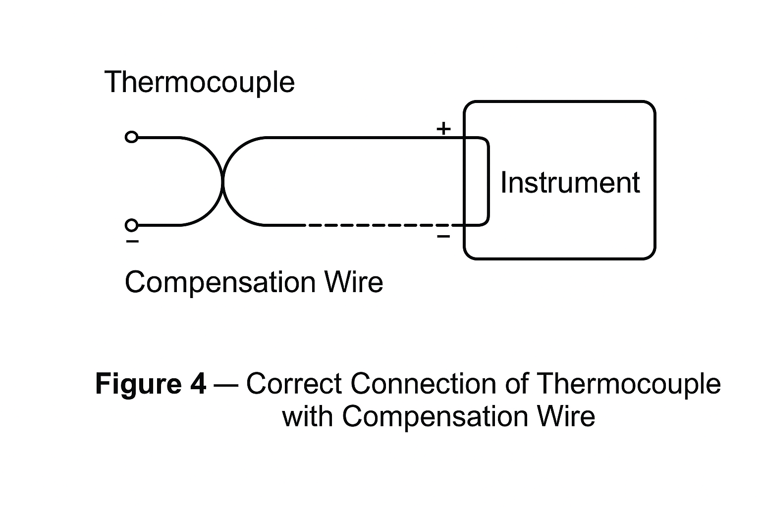
5. Compensation Wires
Purpose: Essential for thermocouple measurement systems to extend the cold junction to the instrument terminal.
Features
Within specified temperature range, thermoelectric characteristics match the thermocouple type.
Reduces influence of ambient temperature variation on accuracy.
Applications
Used in metallurgy, chemical, and high-temperature industries.
Must match thermocouple type (e.g., K-type compensation wire for K-type thermocouples).
Engineering Tips:
Ensure polarity (positive/negative) is correctly connected.
Route away from high-voltage cables.
6. Summary and Selection Flowchart
Instrumentation Cables → Main signal and power transmission.
Insulated Wires → Internal or short-distance connections.
Shielded Cables → Reliable signal transmission in EMI environments.
Compensation Wires → Accurate temperature measurement in thermocouple systems.
7. Reference Standards
To ensure compliance and reliability, cable selection and installation should consider international standards such as:
IEC 60228: Conductors of insulated cables
IEC 60332: Flame retardant properties
IEC 60502: Power cables with extruded insulation
GB/T 9330: Plastic insulated control cables
NEC/ANSI Standards for industrial cable installation