Abstract
The accuracy and reliability of process measurement systems depend not only on the instrument’s design but also on the quality of its installation. In practice, however, inadequate experience, lack of supervision, or misunderstanding of standards often lead to installation errors. Such mistakes may cause measurement deviations, equipment malfunction, or even safety hazards. This article summarizes the most common installation errors observed in engineering practice, along with recommended preventive measures.
1. Improper Selection of Installation Location
Typical Errors
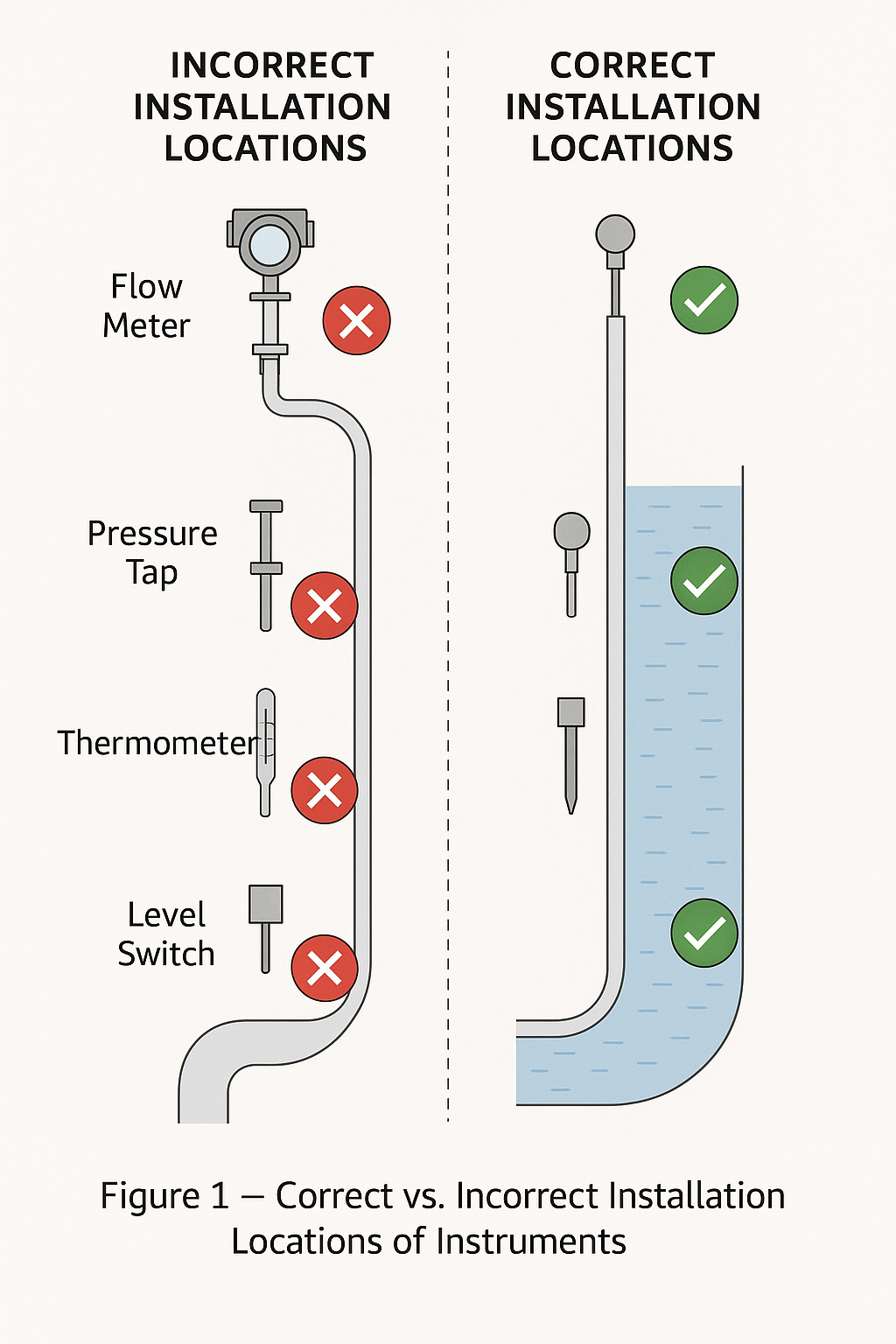
Flowmeters installed too close to elbows, valves, or pump outlets, causing turbulent flow.
Pressure tapping points set at the pipeline’s lowest position, leading to liquid accumulation or blockages.
Temperature probes with insufficient insertion depth, failing to represent actual process temperature.
Level transmitters installed near inlets or agitators, subject to bubbles, flow impact, or mixing disturbance.
Point level switches installed directly above the silo center, where falling material may bury or damage the probe.
Preventive Measures
Follow manufacturer’s installation manual and industry standards; ensure sufficient upstream and downstream straight pipe lengths.
Place pressure tapping points on the upper side or lateral side of pipelines to avoid sediment or liquid accumulation.
Insert temperature elements at least one-third of the pipe diameter, but not less than 100 mm.
Install level transmitters at relatively calm areas, away from inlets or strong turbulence.
Mount point level devices at eccentric positions on silo tops, avoiding the main falling stream of material.
2. Improper Piping Connection and Support
Typical Errors
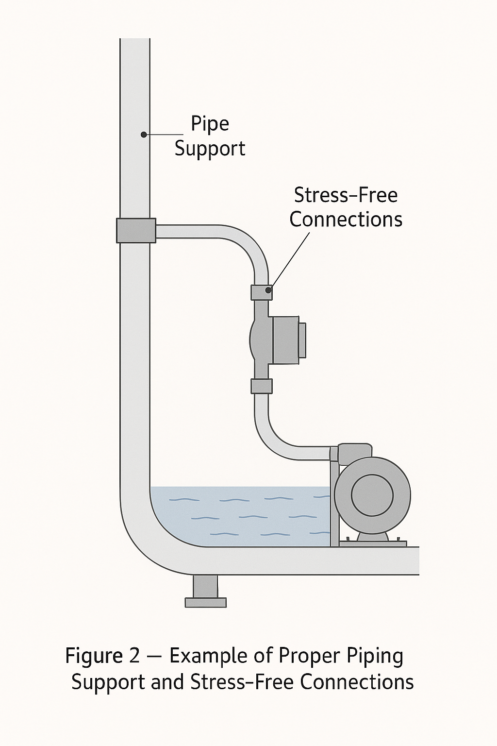
Instruments directly bearing pipeline stress, resulting in housing deformation or leakage.
Secondary instruments or sensors installed without rigid supports, causing vibration during operation.
Flange connections without proper gaskets or uneven bolt tightening, leading to leakage.
Inadequate support for level transmitter impulse lines, causing sagging or vibration.
Preventive Measures
Adjust pipeline alignment before installation; avoid forced connections.
Provide independent supports for heavy instruments or those installed in vibrating environments.
Tighten flange bolts symmetrically and evenly, using suitable gaskets.
Reinforce impulse lines or waveguides to avoid influence from vibration or external force.
3. Poor Grounding and Shielding Practices
Typical Errors
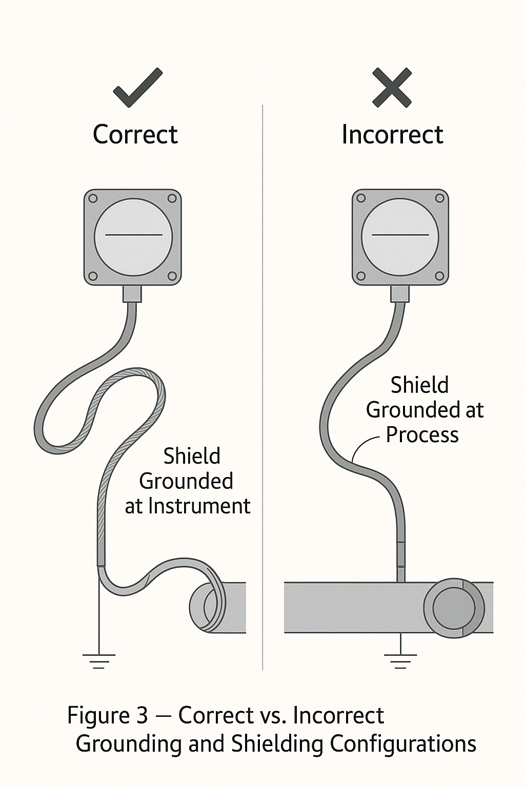
Signal cables not shielded, or shielding left floating, leading to electromagnetic interference.
Instrument grounding shared with power grounding, forming interference loops.
Multiple grounding points creating circulating currents that distort signals.
Ultrasonic or RF admittance level devices installed without proper shielding, causing unstable readings.
Preventive Measures
Use shielded cables and ensure single-end grounding of shields.
Provide independent grounding for instrumentation, complying with resistance specifications.
Avoid multi-point grounding; apply equipotential bonding when necessary.
Route signal lines away from strong power sources and apply additional shielding for non-contact devices.
4. Mismatch Between Process Conditions and Installation
Typical Errors
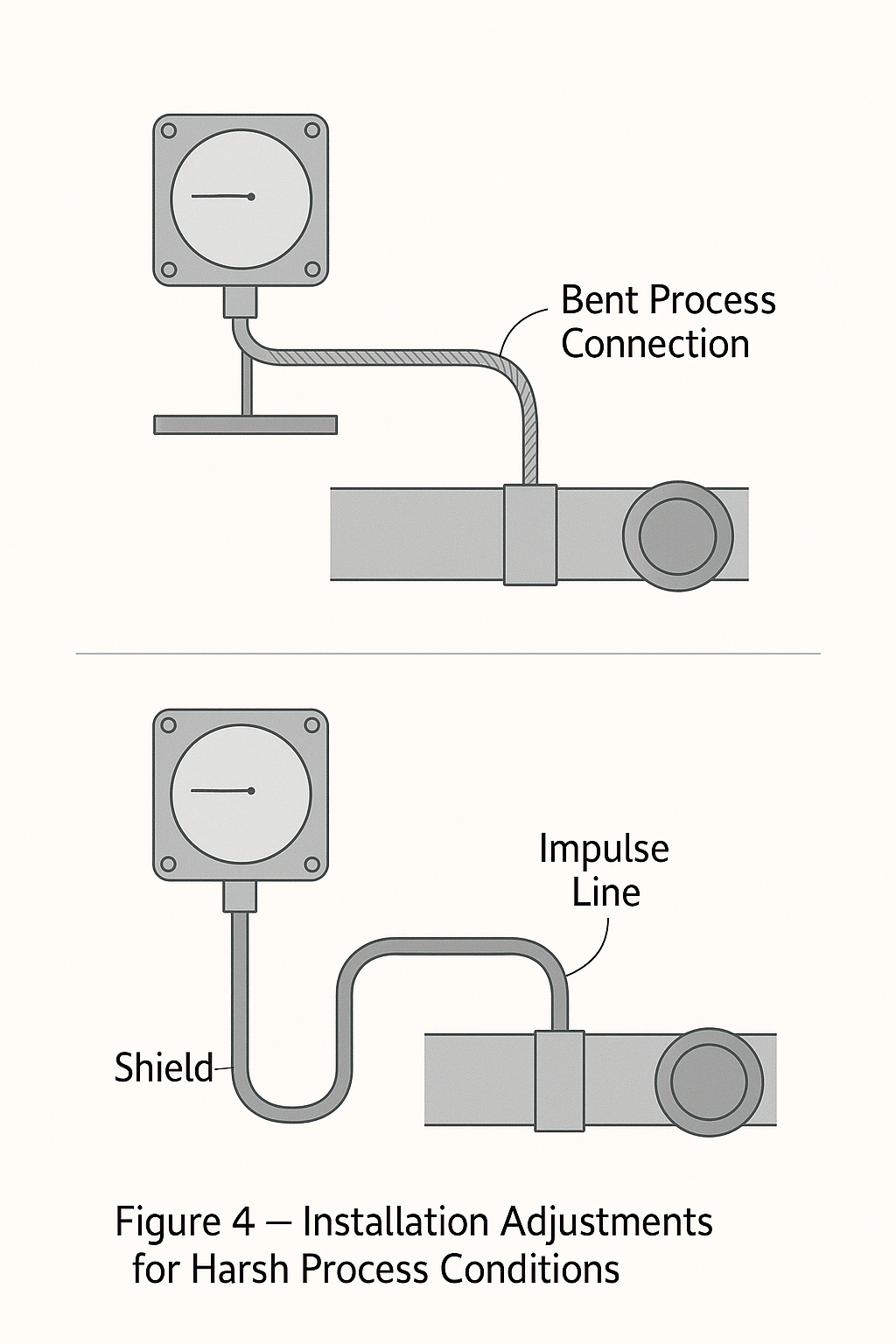
Instruments with unsuitable material or protection grade used in high-temperature, high-pressure, or corrosive environments.
Differential pressure transmitters installed without condensate pots, insulation, or heat tracing.
Gas measurement not considering condensation, resulting in distorted readings.
Magnetic level gauges with poor guiding, causing float sticking.
Radar level transmitters installed at silo domes, subject to wall reflection interference.
Preventive Measures
Select instruments with proper materials and protection grades based on medium and process conditions.
Provide condensate chambers, insulation, or tracing in extreme temperature or corrosive applications.
For gas measurement, select tapping points at the upper part of pipelines to avoid condensation.
Keep guiding tubes of magnetic level gauges smooth and regularly cleaned.
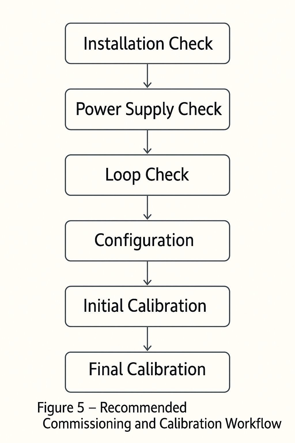
5. Lack of Commissioning and Calibration
Typical Errors
Instruments put into operation without zero-point adjustment or loop testing.
Ignoring installation orientation’s influence on sensor accuracy.
Instruments not calibrated regularly, leading to long-term deviations.
Level transmitter range not matching actual tank height, or blind zone setting inappropriate.
Preventive Measures
Conduct full commissioning before operation, including zero, span, and loop checks.
Install instruments according to manufacturer’s specified orientation.
Establish routine calibration schedules to ensure long-term accuracy.
Configure level/point level instruments with appropriate span and dead zones to avoid false alarms or drift.
Conclusion
The installation of industrial instruments is not merely about physically mounting the device, but a systematic process requiring adherence to standards, attention to detail, and focus on safety. Seemingly minor installation mistakes can cause significant operational risks. By strictly following installation guidelines, strengthening site supervision, and prioritizing commissioning and calibration, plants can ensure both accurate measurement and safe, stable operation of the process system.