Introduction
Vortex flowmeters are widely used in industrial applications to measure the volumetric flow rate of gases, steam, or liquids. Their working principle is based on the Kármán vortex street phenomenon. These flowmeters are known for their high accuracy, low pressure loss, wide range, and minimal maintenance requirements due to their lack of moving mechanical parts. However, during practical applications, various faults can occur, affecting measurement accuracy and reliability. This article discusses six common failure phenomena, their possible causes, and recommended solutions.
1. Vortex Flowmeter Displays a Stable Reading, but the Measured Flow Deviates Significantly
Possible Causes:
Incorrect parameter configuration in the PLC or DCS system.
The presence of square root extraction in the configuration settings.
Errors in temperature and pressure compensation formulas or density query formulas.
Solution:
Verify the system’s configuration and ensure that square root extraction is not applied. Square root extraction is used for differential pressure flowmeters but is unnecessary for vortex flowmeters.
Check the temperature and pressure compensation formulas and correct any errors.
Reconfigure the system parameters correctly to ensure accurate measurement.
2. Flow Measurement Drops to Zero at Low Flow Rates
Possible Causes:
The flowmeter size is too large for the actual application, leading to an excessively high lower detection limit.
The small signal cutoff threshold is set too high, eliminating small flow readings.
Solution:
Increase the sensitivity of the flowmeter to detect smaller flow rates; however, this might result in false readings due to noise interference.
A better solution is to replace the current flowmeter with a smaller diameter model to enhance signal detection at lower flow rates.
If an oversized flowmeter is used, an energy management issue may arise, leading to discrepancies in company records and potential accountability concerns.
3. Significant Measurement Errors at High Flow Rates
Possible Causes:
Vortex flow stability decreases as the velocity increases, potentially leading to unrecognized vortices (wave loss phenomenon).
The sensor or vortex generator may fracture due to excessive turbulence.
Solution:
Ensure that the flowmeter operates within its designated upper limit. When exceeding the designed flow rate, the sensor may fail to capture all vortex signals.
If persistent errors occur at high flow rates, consider replacing the flowmeter with a larger diameter model capable of handling the increased flow.
Advanced signal processing techniques can be employed to improve vortex recognition.
4. Flowmeter Displays a Reading Despite Zero Flow, or Fails to Register Actual Flow Changes
Possible Causes:
Electrical interference or vibration noise mimicking the vortex signal.
Insufficient signal isolation, allowing external interference to affect the measurement.
Solution:
Install an isolation module to filter out interference signals.
Reduce sensor sensitivity to ignore minor noise signals, though this may also reduce the detection of legitimate small flows.
If interference is stronger than the actual vortex signal, additional shielding techniques should be employed.
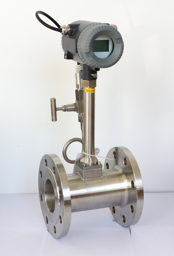
5. Abnormal Fluctuations in Measurement Values
Possible Causes:
Insufficient straight pipe length before and after the flowmeter installation.
Misalignment between the flowmeter and the pipeline, leading to asymmetric flow conditions.
The presence of foreign objects or deposits inside the pipe disrupting vortex formation.
Two-phase flow conditions (gas-liquid coexistence) distorting the vortex signal.
Solution:
Ensure that the required straight pipe lengths upstream and downstream are met (e.g., ≥25D upstream and ≥5D downstream for two 90-degree elbows in the same plane, ≥40D upstream for different-plane elbows).
Regularly inspect and clean the flowmeter sensor to remove any deposits or foreign objects.
If two-phase flow is present, use a separation mechanism before the flowmeter to ensure stable readings.
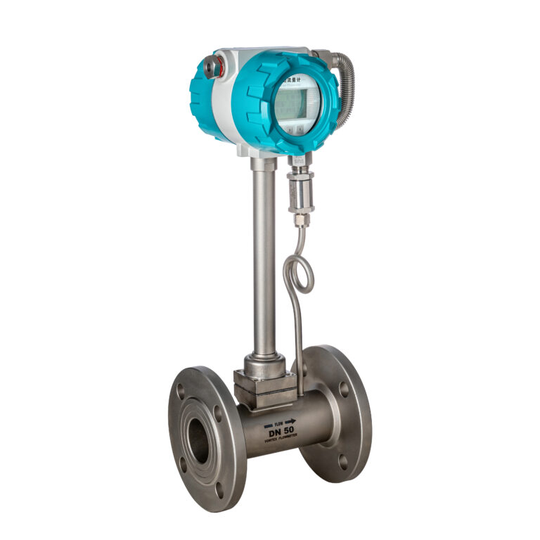
6. Flowmeter Readings Remain Constant Despite Flow Changes or Show Erratic Behavior
Possible Causes:
Mechanical vibration interference exceeding the vortex signal strength.
Strong electromagnetic interference affecting the sensor output.
Solution:
Mount the flowmeter on a vibration-dampened section of the pipeline or use anti-vibration pads.
Apply electromagnetic shielding to prevent interference from nearby high-frequency equipment.
If external interference exceeds the flowmeter’s signal strength, consider using a different measurement technology for highly unstable environments.
Key Takeaways and Best Practices
Proper Sizing Matters: Selecting the right diameter for the vortex flowmeter ensures accurate lower and upper range detection.
Environmental Considerations: Avoid installing near vibration sources, strong electromagnetic fields, or extreme temperature zones.
Regular Maintenance: Periodic sensor cleaning and pipeline checks can prevent measurement inconsistencies.
Straight Pipe Requirements: Adhering to manufacturer-recommended straight pipe lengths improves accuracy.
Signal Processing Improvements: Advanced noise filtering and frequency analysis techniques can enhance signal recognition in challenging conditions.
By understanding these common failure scenarios and implementing best practices, users can maximize the reliability and accuracy of vortex flowmeter measurements in industrial applications.
