Bourdon tube pressure gauges are widely used in industrial processes for pressure monitoring. Due to their mechanical structure and on-site usage conditions, various issues may occur over time. This guide summarizes typical failures, causes, troubleshooting methods, and calibration techniques for Bourdon tube pressure gauges.
1. Typical On-Site Failures and Causes
1.1 No Indication or Pointer Stagnation
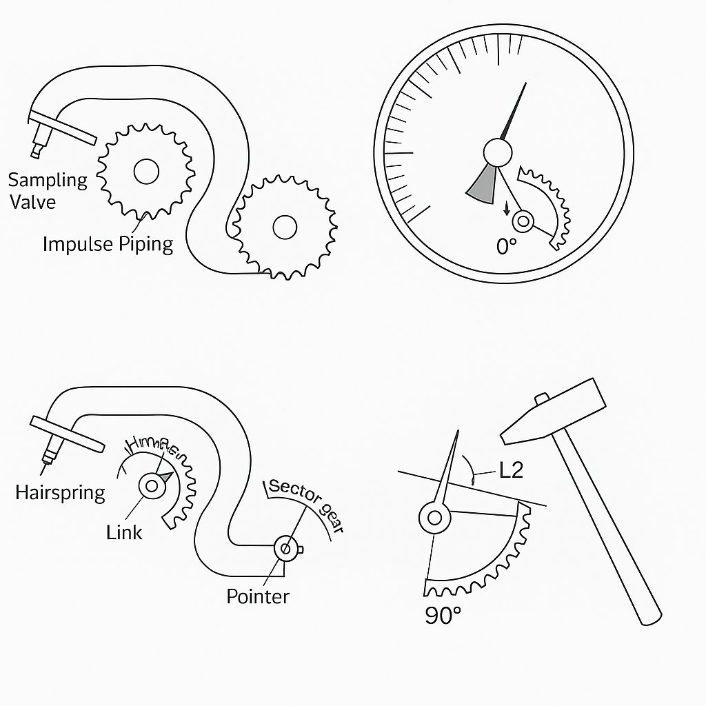
Cause: Blockage in the sampling valve or impulse piping may prevent pressure transmission.
Symptom: Pointer shows no movement or remains fixed despite process pressure changes.
Action: Perform flushing or draining operations. If blockage persists, disassemble and clean the impulse line and valve.
Other Causes: Loose pointer, stuck movement shaft, or mechanical jamming. Gently tapping the gauge housing can help diagnose such faults.
1.2 Pointer Does Not Return to Zero
Cause 1: Sudden pressure surge forces the pointer beyond the mechanical stop.
Cause 2: Loose pointer, damaged hairspring, gear wear, or blocked socket connection.
Cause 3: Hydrostatic pressure from liquid-filled impulse lines when the gauge is installed below the tapping point.
Action: After releasing pressure, check pointer return. If it doesn’t reset, recalibration or repair is required. For installations with isolating fluid, flushing may not be applicable.
1.3 Pointer Jumps or Sticks
Cause: Friction due to loose pointer, contact with dial face or glass, debris in gear train.
Additional Risk: Vibrating equipment may cause gear disengagement.
Solution: Replace with vibration-resistant pressure gauge if anti-vibration measures are ineffective.
1.4 Moisture or Condensation Inside Gauge
Symptom: Water accumulation visible at the bottom of the dial.
Cause: Seal failure or Bourdon tube leakage.
Action: Dismantle for inspection and repair. Replace defective seals or tubes.
2. Calibration and Mechanical Adjustment
2.1 Pointer Installation Method
There are two types of gauges: with or without a mechanical stop pin (“zero stop”).
For gauges with a stop pin, pressurize to the first marked division (e.g., 0.2 MPa on a 0–1.0 MPa gauge), then install the pointer aligned to that point.
For gauges without a stop pin, install the pointer at the zero mark when no pressure is applied.
Secure the pointer tightly using a clockmaker’s hammer. Ensure proper fit of the pointer hole on the movement shaft.
2.2 Adjusting Scale Accuracy
(1) Zero and Full-Scale Point Adjustment
Fix pointer at zero with no pressure.
Apply pressure to full scale; adjust the L2 link length via the calibration screw until the pointer matches the full-scale marking.
(2) Mid-Scale Adjustment
If errors at mid-scale are proportional:
Positive error: lengthen L2.
Negative error: shorten L2.
Ideal angle between the link and sector gear at 50% pressure is ~90°.
(3) Irregular Error Adjustment
Common reasons:
Gear misalignment
Bent gear shaft
Improper link angle
Adjust mechanism alignment or replace worn parts as needed.
(4) Error Pattern Types & Fixes
Type A: Uniform error at all points → reinstall pointer.
Type B: Gradually increasing or decreasing error → adjust L2 length.
Type C: One or two points exceed tolerance → realign link angle or reposition movement.
📌 Tip: When adjusting the calibration screw, use one hand to stabilize the nut and the other to fine-tune with a screwdriver. Aim to minimize the number of adjustments.
3. Common Internal Component Failures
3.1 Distorted or Tangled Hairspring
Cause: Overpressure or mishandling during disassembly.
Impact: Inaccurate zero, erratic pointer movement.
Solution: Replace with a hairspring of the same specification or carefully reshape the existing one.
3.2 Gear Train Wear
Cause: Long-term operation under fluctuating pressure near a fixed point.
Symptom: Pointer sticking, increased hysteresis.
Action: Replace worn sector gear and center pinion with compatible parts.
3.3 Permanent Deformation of Bourdon Tube
Symptom: Pointer fails to return to zero even after calibration.
Solution: Replace the Bourdon tube; it cannot be repaired once plastically deformed.
4. Preventive Measures and Best Practices
🔧 Regularly flush and clean impulse lines to avoid clogging.
🚫 Avoid exposure to sudden overpressure or vibrations.
🛠 Use vibration-resistant gauges in harsh mechanical environments.
📅 Schedule periodic calibration (e.g., annually) to ensure accuracy.
🧰 Always use proper tools during disassembly and avoid bending delicate parts.
📌 Conclusion
Bourdon tube pressure gauges, though simple in design, require precise mechanical integrity and regular maintenance. By understanding common failure modes and calibration techniques, technicians can ensure accurate, safe, and reliable pressure measurement in various industrial applications.