Human minds like a parachute- works best when open.
Chan
9.1 Introduction
In principle, there is no room for argument about what the right flowmeter for the job means. The right flowmeter is the one that will do the job adequately at the lowest possible total cost, including initial cost, and the indirect costs arising from inaccurate measurements and from loss of plant utilization when the flowmeter is out of action.
By this definition, there may be only one type of flowmeter that is right for a
particular job or there may be several; it is certain, however, that there will be
many wrong’ flowmeters for any given situation, either because they will not do
the job adequately, or because they are unnecessarily expensive. The purpose of
this chapter is to help the user to weed out the many wrong flowmeters and
restrict his choice to those that are right, or at any rate, nearly right, for his
application (see Figure 9.1).
This chapter is concerned only with flowmeters for use in pipes, where the
user is confronted with a bewildering variety of types. There is no need to deal
with velocity meters in this way, because there the choice is much more limited, and, in any case, guidance on choosing one of these is given in Chapter 7.
9.2 Cost-consciousness in Flowmeter Selection
The first thing to decide is whether you really need a flowmeter at all. If you
merely wish to know whether the fluid in a pipe is traveling rapidly, or slowly,
or not at all, then a flow indicator as mentioned in section 6.6 will probably
serve the purpose at minimum cost.
If something a little better than this is needed-say, an indication to within
5 or 10% of flow rate-it may still be unnecessary to purchase a meter. You may
actually have the makings of a satisfactory flowmeter already installed. For example, if there should happen to be a change of section in the pipework, then a pressure tapping upstream and downstream of the change of section, suitably linked to a differential pressure gauge or manometer, will provide an acceptable type venturi meter at little cost. Alternatively.,if there is a small-radius bend in the system, one pressure tapping on the inside of the bend and another on its outside wall will, when connected to a suitable differential-pressure gauge,
utilize the centrifugal forces on the fluid to give a reasonable indication of
flowrate. Again, a measurement of pressure loss across a section of pipe where
significant losses are occurring -for example, at elbows or tee-junctions will
often serve the same purpose. In all these cases it will be necessary to provide
some way of relating the differential pressure readings to flow rate, either by a
rough-and-ready calibration, or by calculation based on simple assumptions, or
by relating the differential pressure readings to the known characteristics of the
system.
If none of these simple expedients will serve, the time has come to start
thinking about the purchase of a flowmeter. It is at this point that the selection
table which follows should prove useful.
A flowmeter selection table
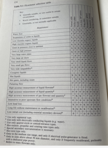
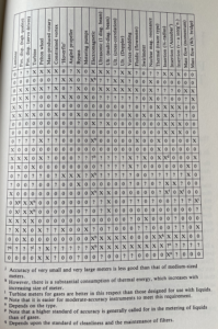
The underlying concept of Table 9.1 is extremely simple. Down the left-hand side are listed 22 requirements that cater for the overwhelming majority of applications likely to arise. Across the top are named all the flowmeter types which have been mentioned in this book in their order of appearance. In each of the 700-odd squares where the rows and columns intersect there is a symbol for, “Yes”, “No”, or “Maybe”, to indicate whether the flowmeter concerned meets that particular requirement.
Filling in some of these squares has been extremely easy. For example, there is no doubt whatever that electromagnetic flowmeters meet the requirement for low head loss and positive displacement meter do not.
However, a great many other squares have presented problems. Take the requirement of very wide rangeability, for instance. How wide is “very wide”? And what does one do about the big variations in performance which occur within one broad type? Positive displacement meters as a class-and yet the best electromagnetic meters are superior in this respect to the worst positive displacement meters.
In deciding upon this and a whole host of other tricky questions I have had to use my own judgment and put into each square the symbol that seemed most reasonable in the light of all the circumstances known to me. No doubt if another flowmeter specialist had been doing the job he would have put different symbols in quite a lot of squares-and, no doubt, in some instances he would have been justified in doing so.
The fact is that this table, like most great oversimplifications, has to be used with caution. It attempts the virtually impossible task of summarising six chapters full of information in two pages and the result is bound to be inadequate, even though I have made free use of footnotes to qualify certain generations. The table must, therefore, be used as a small-scale map to indicate the general area where solutions might be found, and not to provide the last word on any question.
Treated in this way it can save a great deal of time. Use the table to draw up a shortlist of “probables”, and, if necessary, a second list of “possibles”, then go back to the relevant sections of Chapters 3-8 for the detailed information on which to base a final decision.


