The differential pressure (DP) transmitter for boiler drum level measurement is a critical instrument for ensuring safe and stable boiler operation. Deviations between actual water level and transmitter readings may lead to serious risks such as boiler dry-out, overfilling, or even turbine water hammer. This document summarizes five major categories of deviation causes, provides a step-by-step troubleshooting guide, and highlights field cases to support maintenance, calibration, and safe operation.
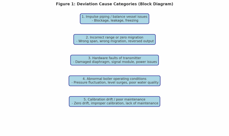
1. Common Causes of Deviation
Category
Typical Symptoms
Key Impact
1. Abnormalities in balance vessel / impulse piping
Blockage by scale or sludge, condensation water not fully filled, leakage at impulse lines, freezing in winter
False high / false low readings
2. Incorrect range or zero migration settings
Wrong span configuration, migration set as opposite sign, 4–20 mA mapping reversed
Systematic deviation in output
3. Hardware faults of transmitter
Damaged diaphragm, signal module failure, unstable power supply, loose wiring
Output signal unstable, frozen, or absent
4. Abnormal boiler operating conditions
Rapid pressure fluctuation, water level surges, carryover, poor water quality
DP reading unstable or delayed
5. Calibration drift / poor maintenance
Long-term zero drift, improper calibration method, lack of routine blow-off
Gradual systematic deviation
2. Troubleshooting Procedure (Step-by-Step)
The principle is “from simple to complex, from signal source to transmitter.”
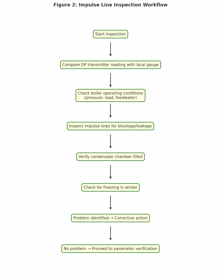
Step 1: Initial On-Site Inspection
Verify true water level: Compare transmitter reading with local level gauge (quartz glass / two-color type).
Check boiler conditions: Ensure steam pressure and feedwater stable.
Inspect impulse lines and balance vessel:
Blow down lines, check for clogging or leakage (soap water bubble test).
Confirm condensation chambers are fully filled.
In winter, check for freezing.
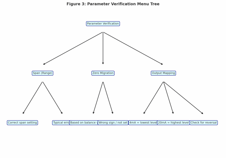
Step 2: Parameter Verification
Access transmitter via HART communicator or DCS. Key items:
Parameter
Correct Setting (Example)
Typical Error
Span (Range)
-6 to +6 kPa (corresponding to -100 to +100 mm water level)
0–12 kPa (output shifted by +6 kPa)
Zero migration
Calculated based on balance vessel height and condensate density
Not set (baseline offset)
Output mapping
4 mA = lowest level (dry), 20 mA = highest level (full)
Reversed mapping
Save and restart transmitter, then re-verify against local gauge.
Step 3: Hardware Diagnosis
Signal simulation: Inject standard DP values (e.g., -5/0/+5 kPa) and verify 4–20 mA correspondence.
Power supply check: Ensure 24 VDC ±10%.
Module diagnostics: Read fault codes (e.g., diaphragm overpressure, communication loss).
Spare unit replacement: Swap with a calibrated spare transmitter to confirm failure.
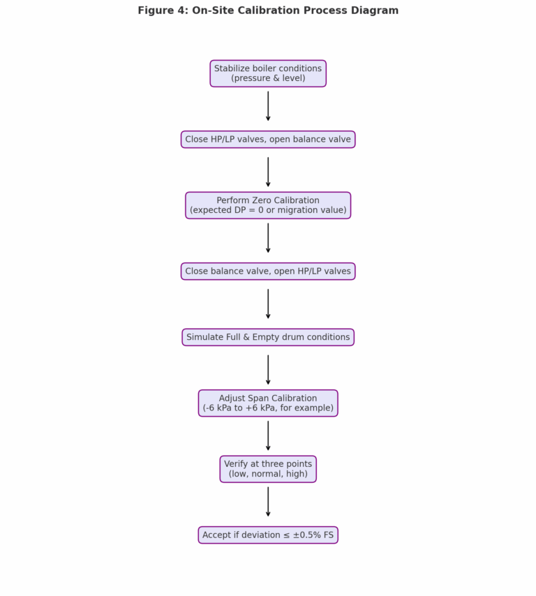
Step 4: Field Calibration
Stabilize boiler load before calibration.
Perform zero adjustment (balance valve open = zero DP).
Conduct span calibration by simulating full water and dry drum conditions.
Verify accuracy at three points (low, normal, high).
Acceptance: ≤±1 mm (level) or ±0.5% FS (DP).
Step 5: Long-Term Preventive Measures
Blow off impulse lines monthly.
Calibrate zero/span every 6 months; full-range calibration annually.
Add insulation/heat tracing to outdoor lines in winter.
Configure DCS compensation for pressure-dependent density changes.
Keep spare transmitters and balance vessel parts in stock.
3. Safety Precautions
Always follow boiler shutdown procedures before disconnecting lines.
Record all original parameters before calibration to prevent configuration loss.
Work with boiler and maintenance teams for welding or vessel replacement.
4. Field Case Studies
Case 1: Clogging by black deposits
Symptom: One drum transmitter output lower than others.
Cause: 1 mm orifice plate at flange blocked by black deposits.
Solution: Cleaning and reinstalling restored normal reading.
Case 2: Leakage at transmitter connection
Symptom: Large deviation between left and right side drum levels in winter.
Cause: Poor-quality gasket, improper reinstallation after antifreeze water drain.
Solution: Replaced gasket and re-tightened, restored accuracy.
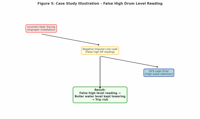
Case 3: DCS deviation due to improper impulse line installation
Symptom: DCS level reading -50 mm, local gauge -330 mm.
Cause: Heat tracing installed incorrectly; negative impulse line leaking; DCS using “high-value selection” logic.
Accurate boiler drum level measurement is fundamental for safe boiler operation. By systematically analyzing deviation causes, following structured troubleshooting steps, and implementing preventive measures, plant operators can significantly reduce false readings, improve safety, and extend transmitter service life.