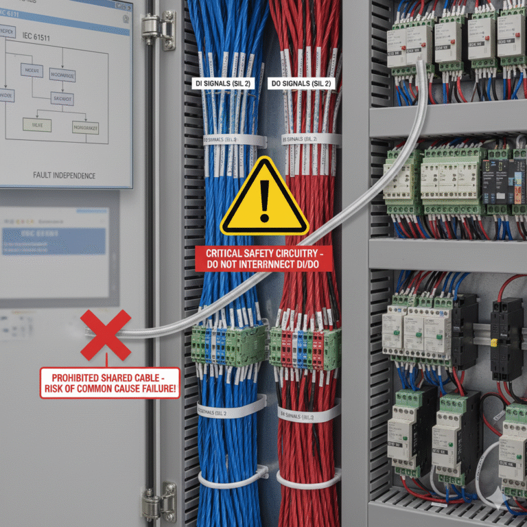
In the design and installation of Safety Instrumented Systems (SIS), one seemingly “convenient” practice—routing Digital Input (DI) and Digital Output (DO) signals through the same multi-core cable—may present serious risks. Did you know that this wiring method is not only discouraged, but also prohibited in many high-reliability environments? In this article, we will explore the potential interference, fault propagation, and standard requirements behind this issue.
Why DI and DO Signals Should Not Share a Cable in SIS
In SIS systems, it is strongly advised to avoid routing DI and DO signals through the same cable. This practice is considered poor engineering practice and is generally not acceptable in systems that prioritize high integrity and reliability.
For critical DI and DO signals involved in Safety Instrumented Functions (SIF), independent cabling is the preferred and safest solution.
DI Signals: Typically use twisted-pair shielded cables (twisted pair + overall shielding), with the shield grounded at a single point at the controller end.
DO Signals (especially those driving inductive loads): It is recommended to use shielded cables, with additional surge suppression devices (such as flyback diodes, RC snubber circuits, or varistors) added at the load end to suppress transient voltages. The grounding of the shield should be determined based on the load and interference conditions (sometimes it is better to ground at the load end).
Interference Risks
DO signals—particularly when driving relays, solenoid valves, or motor starters—generate significant voltage and current transients during switching operations, especially when disconnecting inductive loads. These transients can interfere with DI signals transmitted through nearby cables due to capacitive and inductive coupling.
DI signals typically represent critical field device statuses (e.g., valve limit switches, pressure switches, emergency stop buttons). Interference could lead to incorrect state transitions (e.g., a “valve closed” signal when the valve is open), resulting in:
Unnecessary safety actions: For example, a false “valve closed” signal could incorrectly allow system startup when the valve is actually open, or a false “valve open” signal could trigger unnecessary shutdowns.
Failure to execute necessary safety actions: A false “high pressure” or “emergency stop pressed” signal could be ignored, preventing the SIS from detecting real hazard conditions.
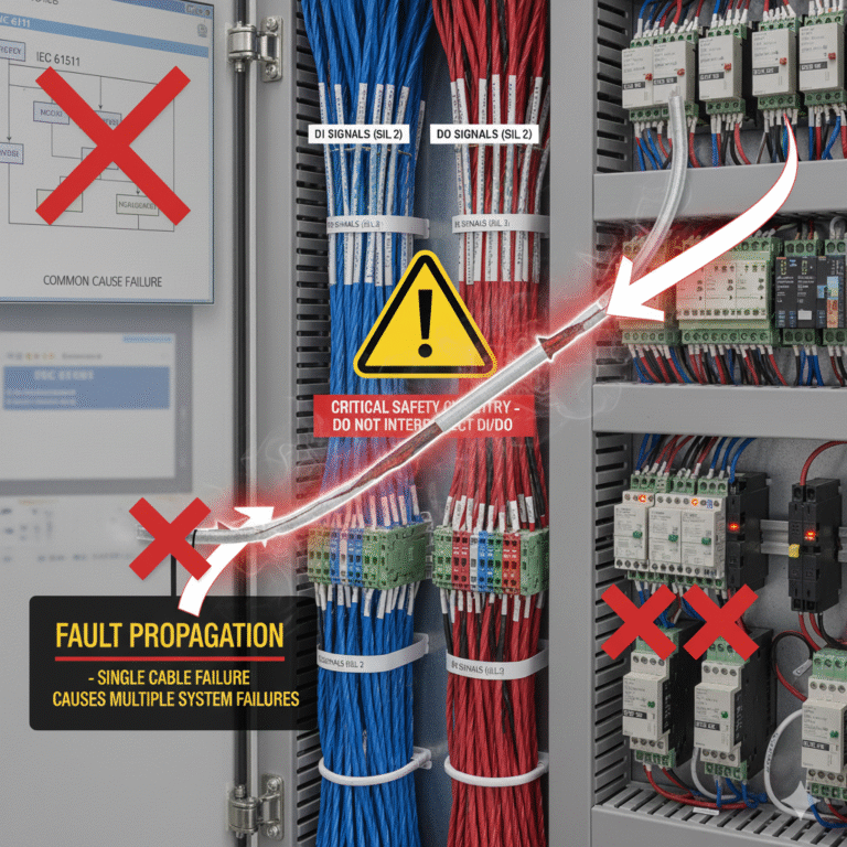
Fault Propagation
If a physical fault occurs in the common cable (such as crushing, cutting, water ingress, or corrosion), it could simultaneously affect both the DI and DO loops.
In SIS design, a core principle is fault independence—the failure of one loop should not compromise another safety loop or create hazardous side effects. Sharing a cable directly violates this principle and significantly increases the risk of common-cause failures, where a single cable fault could lead to multiple safety functions failing simultaneously.
Grounding Loops and Potential Differences: If DI and DO signals are connected to different devices that have different ground potentials (a common scenario in industrial environments), the shield or reference ground of the shared cable may create a ground loop. Ground loops introduce additional noise currents, which can further interfere with sensitive DI signals.
Diagnostic and Maintenance Challenges
Using a common cable complicates fault diagnosis. When a DI signal malfunctions, it becomes difficult to determine whether the issue lies with the field device, the wiring, or interference from the DO signal on the same cable.
Additionally, maintenance or testing of the DO loop may inadvertently affect the DI loop, leading to further complications in troubleshooting.
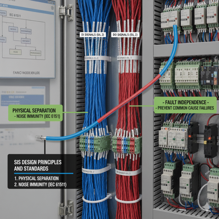
SIS Design Principles and Standards
According to IEC 61511 / ISA 84.00.01 (Functional Safety for Process Industry Safety Instrumented Systems):
Avoid Common Cause Failures: The design must prevent a single failure from affecting multiple safety functions (Clause 11.2.4). Sharing a cable is a clear source of common-cause failure.
Noise Immunity: SIF loops must be designed to withstand expected electromagnetic interference (EMI) (Clause 11.2.13). Sharing a cable between DI and DO signals increases the risk of internal EMI.
Physical Separation: Standards encourage or require physical separation between safety and non-safety circuits, or between different safety circuits, to reduce interference and common-mode fault risks. DI and DO, as separate safety function loops, should follow this principle.
Good Engineering Practice (GEP): In functional safety, isolating DI signals from interference-prone DO signals—especially those driving inductive loads—is the most basic and widely accepted practice.
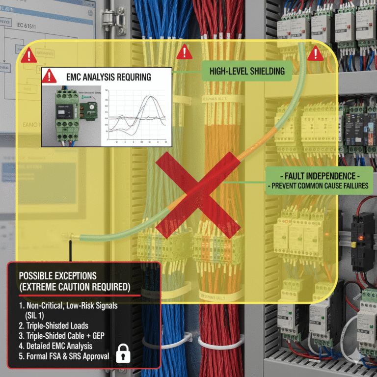
Possible Exceptions (Extreme Caution Required)
In extremely limited cases with very low risk, sharing a cable might be considered, but it is not recommended as a standard practice:
Non-critical, low-risk signals: DI and DO signals may belong to the same SIF but have a negligible impact on the system’s safety.
Static DO signals: If the DO signal is static (rarely switched), and the load is purely resistive (no inductive elements), the interference generated is minimal.
High-level shielding: Using triple-shielded cables (overall shield + individual shielding for each pair) and ensuring high-quality, low-impedance grounding at both ends of the shields.
Detailed EMC analysis: A detailed Electromagnetic Compatibility (EMC) analysis should demonstrate that DO-induced interference will not cause DI signal malfunctions and that the SIL requirements are met. This often requires complex simulations or real-world testing.
Safety Assessment and Approval: This deviation must be explicitly recorded in the Safety Requirements Specification (SRS) and approved by all relevant parties (owners, designers, SIL verification teams) through a Functional Safety Assessment (FSA).
Conclusion
In SIS systems, independent cabling for DI and DO signals is critical to ensure maximum safety, reliability, and fault independence. The risks associated with sharing a cable far outweigh any potential savings in cost or space. Any decision to deviate from this principle must undergo rigorous justification, risk assessment, and formal approval.