Cable laying standards are essential to ensure the safety, stability, and longevity of cable systems in industrial and infrastructure projects. This guide outlines key procedures and technical considerations, covering pre-installation checks, installation in various environments, cable fixing and spacing, joint and terminal production, and safety precautions.
1. Pre-Installation Preparation
1.1 Cable Inspection
Visual Check: Ensure the outer sheath is free from damage, dents, or deformation. Confirm that end caps are securely sealed to prevent moisture ingress.
Specification Verification: Check model, conductor size, core count, and rated voltage against design documents.
Insulation Resistance Test: Use a megohmmeter to confirm insulation resistance:
For cables rated ≤1kV: ≥10 MΩ
For 10kV cables: ≥400 MΩ
Record results for documentation.
1.2 Route Planning
Site Survey: Identify obstacles like pipelines or buildings; avoid areas with heat or corrosive substances.
Obstacle Clearance: Remove construction debris and plan bypasses or protections.
Length Allowance: Allow extra length at joints, terminals, and bends.
2. Laying Requirements for Different Environments
2.1 Direct Burial
Burial Depth: Not less than 0.7m (1m in farmland); below frost line.
Layering:
100mm of fine sand/soil above and below cable
Cover with concrete slab or brick (extend 50mm beyond cable sides)
Markers: Place at every 50–100m, bends, joints, and building entries.
2.2 Cable Trenches
Dimensions: Depth ≥600mm, with a 0.5% drainage slope.
Supports:
Hot-dip galvanized steel brackets
Spacing:
Horizontal: ≤1m (power), ≤0.8m (control)
Vertical: ≤1.5m (power), ≤1m (control)
Arrangement:
Separate high- and low-voltage
Power above, control below
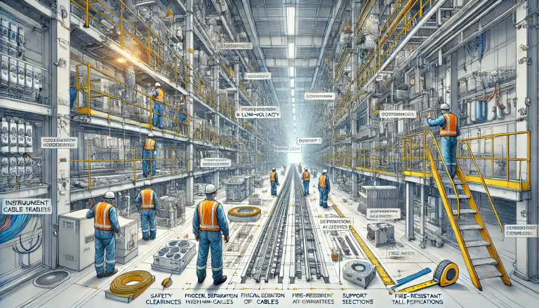
2.3 Cable Trays
Tray Selection:
Ladder, perforated, or solid types
Anti-corrosive materials for harsh environments
Filling Ratio:
≤40% for power cables
≤50% for control cables
Installation:
Firmly fixed, aligned
Use special connectors
Tray bends must match cable bending radius
Layered Laying:
Arrange by voltage and function
3. Cable Fixing and Spacing
3.1 Fixing
Method: Use nylon ties or clamps; do not damage sheath.
Spacing:
Vertical or ≥45° tilt: every 2m
Horizontal ends, joints, bends: must be fixed
Horizontal laying:
Power: every 5–10m
Control: every 8–10m
3.2 Spacing Between Cables
Parallel Laying:
≤1kV power: ≥35mm (not less than cable diameter)
1kV power: ≥250mm
Power vs Control: ≥150mm
Crossing:
Maintain ≥250mm clearance within 1m each side of crossing
Use sleeves or protective devices if clearance is limited