1. Key Factors Affecting Actual Accuracy
1.1 Fluid Properties Deviating from Ideal Conditions
Viscosity and Reynolds Number Effects
Stated accuracy is often based on calibration with low-viscosity fluids like water (1 mPa·s). High-viscosity media (e.g., lubricating oil at 50 mPa·s) significantly alter flow behavior:
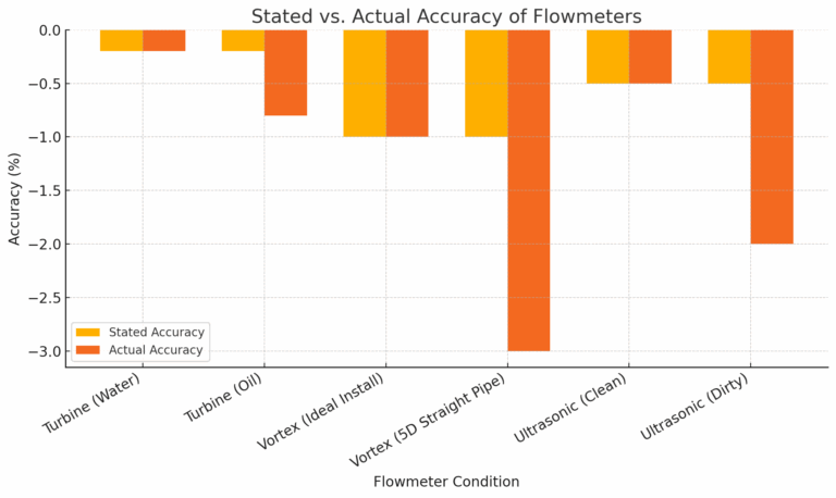
Turbine flow meters show reduced rotor speed due to increased resistance, resulting in lower indicated flow. Error may increase from ±0.2% to ±0.8%.
Differential pressure (DP) flow meters (e.g., orifice plates) exhibit significant flow coefficient deviation at low Reynolds numbers (Re < 10⁴), exacerbating nonlinearity.
Temperature and Pressure Impact on Fluid Density
Liquids: Minor density changes (e.g., water at 80°C is ~0.3% less dense than at 20°C) have limited effect on volumetric flow but affect Coriolis mass flow meters, which depend on density-related vibration frequency.
Gases: Increased pressure drastically raises gas density. Without compensation, volumetric flow meters (e.g., vortex) can underestimate flow by up to 87% in 0.8 MPa compressed air systems.
Contaminants and Flow Disruptions
Solids and bubbles may damage turbine rotors or attenuate ultrasonic signals. In wastewater, sensor fouling can increase error from ±0.5% to ±2.0%.
1.2 Installation and Commissioning Errors
Inadequate Straight Pipe Length
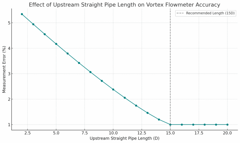
Devices like vortex and DP flow meters require fully developed flow. For example, if upstream straight pipe is only 5D instead of 15D, vortex meter error may expand from ±1.0% to ±3.0%.
Mechanical Stress and Vibration
Flange stress may deform Coriolis meter tubes, altering resonant frequency and adding ~0.5% error.
Pipe vibration introduces noise in vortex meter piezoelectric sensors, reducing signal-to-noise ratio (especially at low velocity).
1.3 Environmental and Operational Impacts
Electronic Component Drift due to Temperature
Operating outside rated temperature range (e.g., above 60°C) can degrade ADC resolution and amplifier stability. An electromagnetic flow meter may show increased error from ±0.3% to ±0.7% after prolonged 80°C exposure.
Aging and Lack of Calibration
Component wear (e.g., turbine bearings) and sensor drift (e.g., capacitor aging) accumulate over time. Uncalibrated ultrasonic meters (over 2 years) may show an average error increase of 0.8%.
1.4 Pressure and Velocity Effects
Pressure Effects
Density sensitivity: In gas measurement, pressure directly alters density. Uncompensated volumetric meters will show increasing deviation as pressure rises.
Structural deformation: In high-pressure pipelines (e.g., PN40), even minor tube contraction (e.g., 0.1% in EMF stainless tubes) leads to measurable errors.
Velocity-Related Errors
Low velocity: Signal-to-noise ratio drops below minimum velocity threshold (e.g., <0.5 m/s in turbines), increasing error up to ±1.5%.
High velocity: Above upper limit (e.g., >15 m/s in ultrasonic meters), time resolution decreases and error may double.
Combined Pressure-Velocity Effects
In throttling conditions, pressure drop and velocity rise together:
Lower pressure → reduced gas density → overestimated volumetric flow.
Higher velocity → deviation in flow coefficient (e.g., vortex meters), compounding error.
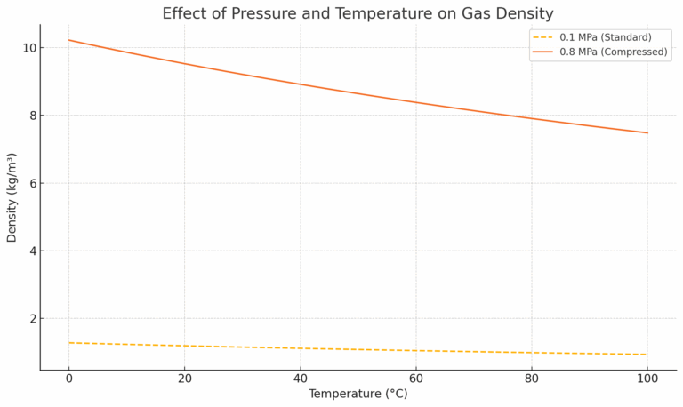
Table: Typical Accuracy Variations of Common Flowmeter Types
| Flowmeter Type | Stated Accuracy | Typical Operating Conditions | Deviation in Actual Accuracy | Key Influencing Factors |
|---|---|---|---|---|
| Turbine Flowmeter | ±0.2% to ±0.5% FS | High-viscosity fluids, suspended solids | Error magnified by 0.5–1.0× | Rotor wear, Reynolds number effects, bearing friction |
| Electromagnetic (EMF) | ±0.5% to ±1.0% | High-temperature media, misalignment, electrical particles | Error increased by 0.3–0.8% | Liner deformation, EM interference, signal amplitude |
| Vortex Flowmeter | ±1.0% to ±1.5% | Compressed gases, short upstream pipe, vibration | Error increases to ±2.0%–±3.0% | Density compensation error, unstable flow, sensor noise |
| Orifice Plate (DP) | ±1.5% to ±2.0% | High-pressure gas, outdated calibration, low velocity | Error increases to ±3.0%–±4.0% | Orifice wear, flow coefficient drift, Reynolds sensitivity |
| Coriolis Flowmeter | ±0.1% to ±0.3% | High-pressure liquids, drastic temperature changes | Error increased by 0.1–0.4% | Tube elasticity, fluid density fluctuation, thermal response |
3.3 Dynamic Compensation of Pressure and Flow Effects
Real-Time Multi-Variable Compensation
Integrate pressure (±0.1%) and temperature (±0.2°C) sensors to convert actual to standard or mass flow via PLC or smart transmitter.
Coriolis meters inherently measure mass flow but still require temperature compensation for thermal expansion and frequency stability.
Nonlinear Algorithm Correction
Build empirical correction models using calibration data.
Use neural networks to map pressure/velocity to correction coefficients.
Apply segmented linearization for non-linear sensors (e.g., ultrasonic, EMF) and adaptive filtering to reduce low-velocity noise.
3.4 Full-Life-Cycle Maintenance
Scheduled Calibration and Diagnostics
Trade meters: annual calibration; process control: every 2–3 years.
Use high-precision methods (e.g., gravimetric, volumetric; uncertainty ≤0.05%).
Preventive Maintenance
Clean sensor surfaces regularly in particulate media (e.g., ultrasonic quarterly).
Inspect seals in high-pressure systems (e.g., EMF lining cracks) to prevent mechanical deformation.
4. Summary: A Systematic Approach to Precision
The gap between stated and actual flowmeter accuracy stems from idealized assumptions clashing with complex real-world conditions. Pressure and velocity variations alter fluid properties, structural stability, and flow profiles—all of which influence measurement precision.
A comprehensive approach—appropriate selection, correct installation, dynamic compensation, and regular maintenance—is key to minimizing these differences and ensuring trustworthy data.
Looking Ahead:
As IoT, smart sensors, and machine learning mature, future flowmeters will feature advanced self-diagnostics, self-calibration, and digital twin-based prediction models. These innovations will further bridge the gap between laboratory precision and field reality, enabling the next generation of intelligent process control.