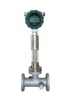
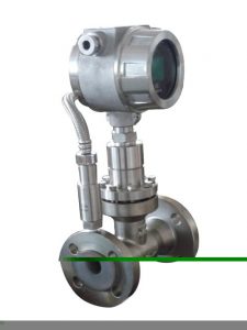
Asphalt flowmeter adopts the principle of differential target flowmeter to ensure the durability, practicability, and long service life of the asphalt flowmeter. At the same time, the asphalt flowmeter has the advantages of high measurement accuracy and good stability.
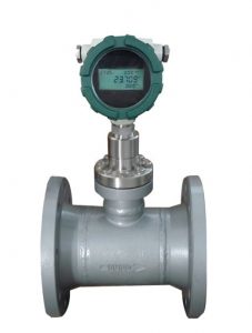
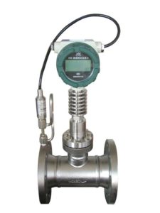
A flow measuring instrument is used for measuring various asphalt flow rates. The whole set of asphalt flow meters is composed of flow sensors (force sensors), an intelligent LCD display, measuring tubes, and other components. An asphalt flowmeter can also be applied to the measurement of various pure dirty and corrosive mediums.
Because of its large rangeability, high accuracy, stable performance, ability to measure high temperature, high viscosity liquid, easy installation, convenient operation, etc. It is suitable for fluid measurement in industrial sectors such as petroleum exploration, refining, chemical industry, commerce, and oil storage.
Data:
- Diameter: DN15~DN500mm
- Nominal pressure: 0.6~42MPa
- Working temperature: -200℃~-30℃
- Accuracy: ±0.1
- Range ratio: 1:8
- Shell: carbon steel; stainless steel (or tailor-made according to user requirements)
- Power supply mode: no power supply is required
- Output signal: 4~20mA two-wire system; pulse 0~1000HZ; RS232/RS485 (or according to user requirements)
- Protection level: IP65 or IP67
- Explosion-proof mark: intrinsically safe ExiallCT4; explosion-proof ExdllCT4
- Executive standard: Q/BET05-06
- Meter display: cumulative flow; instantaneous flow; working condition temperature; working condition pressure (only available for temperature and pressure compensation); rod-shaped full-scale percentage; fault self-check
- Connecting flange: national standard (GB/T) series; chemical (HG) series; mechanical (JB/T) series; it can also be made in consultation with customers.

Feature:
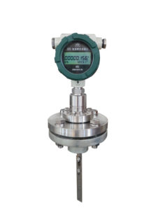
- The whole asphalt flow meter has no movable parts in the design, and the asphalt flow meter structure is easy to disassemble
- Asphalt flow meters can choose a variety of anti-corrosion and high and low-temperature resistant materials (such as Hastelloy, titanium, etc.)
- The whole machine can be made into a fully sealed, no dead angle (welded form), without any leakage points, and can withstand 42MPa high pressure
- The asphalt flow meter is equipped with a self-checking program, and the fault phenomenon is clear at a glance
- The sensor is not in contact with the measured medium, there is no wear and tear of parts, and it is safe and reliable to use
- The dry calibration method can be used on the spot, that is, the weight hanging method is used. A single key operation can complete the calibration
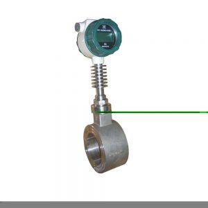
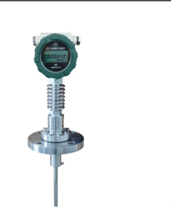
- There are a variety of installation methods to choose from, such as online asphalt flowmeter, low installation cost
- With integrated temperature and pressure compensation, directly output quality or standard
- Asphalt flowmeter has optional small-signal removal, non-linear correction, filter time optional
- It can accurately measure the flow of gas and liquid under various conditions of normal temperature, high temperature 500 degrees, and low temperature of -200 degrees.
- The measurement is accurate, and the accuracy can reach 0.2%
- Good repeatability, generally 0.05~0.08%, fast measurement
- The pressure loss is small, only about 1/2△P of the standard orifice plate
- Strong anti-interference and anti-impurity ability
- The flow rate range can be changed by replacing the flow block (target) according to actual needs
- Low-power battery on-site display, which can directly read the displayed value online, and the display screen can read instantaneous and cumulative flow and percentage bar graphs at the same time
- The installation is simple and convenient, and it is extremely easy to maintain
- A variety of output forms can transmit various parameters remotely
- Strong vibration resistance and pulsating flow can be measured within a certain range
Installation and use:
- The installation direction of the meter should be such that the direction of the arrow shown on the meter shell is consistent with the direction of liquid flow, and the installation position should be easy to read.
- The meter should be installed at room temperature as much as possible, and should not be installed in places with harmful gases and strong heat radiation, to prevent damage to the counterpart of the meter.
- The asphalt shaft in the instrument should be installed in a horizontal position as much as possible, that is, the dial should be installed in a vertical position (the index “0” should be on top) to reduce the friction between the asphalt gear and the housing and reduce the wear of the parts. Due to the different installation positions, in order to facilitate reading, the counter (meter head) can be rotated 90° or 180°.
- Before the instrument is installed, the pipeline must be thoroughly cleaned. In the entire pipeline system, if there is no strict filtering device, a filter should be installed in front of the instrument to prevent impurities from entering the meter.
- The meter should be installed at the outlet of the pump, and the flow regulating valve should be installed downstream of the meter. When in use, first open the upstream shut-off valve, and then slowly open the downstream flow regulating valve or shut-off valve. It is strictly forbidden to open or close suddenly.
- When the meter is in use, the meter should be filled with liquid. There should be no gas in the measured liquid, otherwise, the mixed volume of gas and liquid will be measured, which will make the measurement inaccurate. When there is gas in the liquid, a gas separator must be installed upstream of the instrument.
- The flow in the pipeline should not increase or decrease sharply. Pipe vibration, hydraulic shock, and sharp pressure fluctuations should be avoided, otherwise, they will affect the normal operation of the instrument.
- When the flow rate exceeds the specified maximum flow rate, the asphalt will wear out as the speed increases, and the pressure loss will increase sharply. Avoid using it. Below the minimum flow rate, although it can still be measured, the error increases. The starting flow of the flowmeter is about 2% of the maximum flow, and the normal working flow is preferably 70%-80% of the maximum flow.
- When measuring high-viscosity liquids, the liquid is generally heated to reduce the viscosity, and then circulates in the pipeline. When the meter is deactivated, the liquid filled with the meter becomes viscous due to cooling. If it is restarted, it must be heated outside the meter body with steam or other methods to reduce the viscosity of the liquid. It can be used after the viscosity of the liquid in the meter decreases. Otherwise, the mucus will bite the transmission parts and cause damage to the meter.
- The temperature of the liquid to be measured should not be higher than the specified value, otherwise, the meter will not work normally or even get stuck. Liquid temperature changes can also cause additional errors due to viscosity. In addition, the increase in temperature also causes the volume of the crescent space to increase, which is because the meter “walks slowly”, when the measuring chamber is made of cast iron and the oval gear is made of cast aluminum, the additional error is +0.14%/100°C.
- When each instrument leaves the factory, it is calibrated with No. 7 mechanical oil at room temperature. At room temperature, the viscosity of the oil is about 10mpa.s. If the viscosity of the liquid used by the user differs greatly from this, the double-layer gear can be replaced.
- It is strictly forbidden to sweep steam and water through the meter.
Precautions:
It is not allowed to install valves, elbows and other components that greatly change the fluid flow state directly at the front and rear ends of the flow meter measuring tube. If you need to install valves, elbows, and other components on the front and rear pipes of the flowmeter, you should also try to ensure the length of the front and rear straight pipes.
Common malfunctions:
- When the flow rate of the measured medium in the pipeline is zero, the instantaneous flow value indicated by the flowmeter is not zero. The main reasons for this phenomenon are:
a. The level of the flowmeter before and after installation is inconsistent so that the target piece and the target rod are inclined to produce an axial horizontal component of force, resulting in an instantaneous flow.
b. The flowmeter is running for a long time, and the internal stress of the sensor changes slightly.
c. During installation or operation, severe overload causes zero drift. The above three methods can refer to the steps and methods of clearing the flowmeter.
- Poor grounding of the flowmeter housing;
Solution: the user re-grounds.
- The target piece, target rod, and measuring tool are jammed by debris.
Treatment method: close the front and rear valves of the flowmeter, use a tool to loosen the connecting bolts between the flowmeter transition part and the measuring tube, and gently shake the transition part or take it out. After cleaning the debris, reset it as it is.
- The indication value increases abnormally during the working process of the flowmeter. The main reasons for this phenomenon are A. There are filamentous and ribbon-shaped debris hanging on the target and the target rod;
Treatment method: Refer to the method of handling debris.
B. Under high junction conditions, the target sheet and the target rod will form a serious bond, which increases the projected area of the target plate of the force-bearing element along the axis of the measuring tube, that is, the annular flow area between the target sheet and the measuring tube decreases, and then the same Under the flow rate, the force on the sensor increases, which eventually leads to an abnormal increase in the flow rate indication;
Processing method: remove the transition parts, and use tools to remove the target piece and target rod and the masonry on the inner wall of the measuring tube.
- The measurement error is large, and there are many reasons for this phenomenon. The main reasons are the following: A: The relative concentricity of the flow meter and the connecting pipeline is greatly misaligned during installation, and the sealing gasket is not concentric, thus forming a throttling resistance, which greatly affects the flow state of the measured medium.
Treatment method: adjust the installation status.
B. The straight pipe sections before and after the flowmeter are too short, and elbows and valves are installed directly in front of the flowmeter, which greatly interferes with the flow state of the measured medium;
Treatment method: install in accordance with the instructions or calibrate the flowmeter on the spot.
C. Leakage of bypass pipeline;
Treatment method: check and replace the bypass pipeline.
D. There is band-shaped debris around the target, which increases the force on the target;
Treatment method: Refer to the previous method of handling debris.
- The flowmeter has no indication or no signal. The main reasons are as follows: A. The power supply is in poor contact or falls off;
Solution: For flow meters with batteries, check whether the batteries are installed securely, whether the contacts are good, and whether the batteries have electricity. For the external power supply, check whether the connection between the connecting wires is intact, whether the wires are conductive, and whether the external power supply is normal.
B. The flowmeter circuit is damaged;
Treatment method: return to the factory for repair.
C. The display screen is damaged;
Treatment method: return to the factory for replacement.
D. The user signal receiving system fails;
Treatment method: check and troubleshoot.
- The indicated value is always zero during the operation of the flow meter. The main reasons for this phenomenon are: A. The force-bearing component (target) falls off, causing the sensor to be unable to sense;
Treatment method: Assemble targets of the same specification.
B. The flowmeter sensor has no voltage output signal;
Processing method: First, determine whether the sensor is damaged, the specific method is to see whether the sensor data has changed.
C. The flow rate of the measured medium is too small, which is lower than the minimum scale flow rate of the flowmeter;
Treatment method: return to the factory to replace the stress component.