In the world of industrial automation and electrical safety, terms like protective earthing (PE) and enclosure grounding are often used interchangeably. However, while they may physically share the same grounding point, their purposes, design principles, and regulatory implications are fundamentally different. Understanding this distinction is crucial for engineers, electricians, and system integrators alike.
✅ What Is Protective Earthing?
Protective Earthing (PE) is a mandatory safety feature that involves connecting all exposed conductive parts of an electrical system—such as metal enclosures, motor casings, or instrument housings—to the earth. Its primary function is to protect human life in case of insulation failure or accidental live contact.
If a fault causes a live wire to touch the metal enclosure, the PE connection ensures that the fault current flows directly to the ground, triggering a circuit breaker or fuse, thus preventing electric shock.
Key Characteristics:
Required by safety standards (e.g., IEC 60364, NEC)
Uses green/yellow conductors (in most standards)
Connects to main grounding bar or earthing system
Ensures automatic disconnection of supply during faults
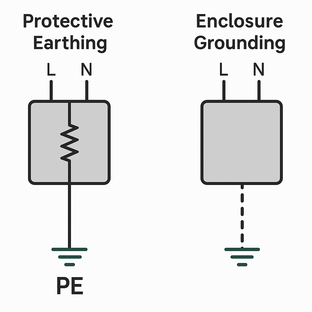
✅ What Is Enclosure Grounding?
Enclosure Grounding, on the other hand, generally refers to grounding metal enclosures for purposes such as:
Electromagnetic interference (EMI) shielding
Voltage equalization
Lightning protection
Minimizing capacitive coupling in high-frequency circuits
It is a functional grounding that may or may not be connected to the protective earth system. In many designs, it is done to stabilize signal integrity, especially in instrumentation, control cabinets, or RF systems.
Key Characteristics:
Not always mandatory by safety standards
May use shielded cables or bonding straps
Focused on performance and EMI compliance
Often used in IT equipment, PLC panels, or signal wiring
✅ Can They Be Combined?
Yes — in many practical applications, protective earthing and enclosure grounding use the same physical connection point, such as a cabinet’s grounding terminal. This is common in compact installations and helps simplify wiring.
However, the design intent must always be clear:
If the purpose is human safety, it must comply with PE design rules.
If the purpose is signal shielding, the grounding path must be designed to minimize noise and avoid ground loops.
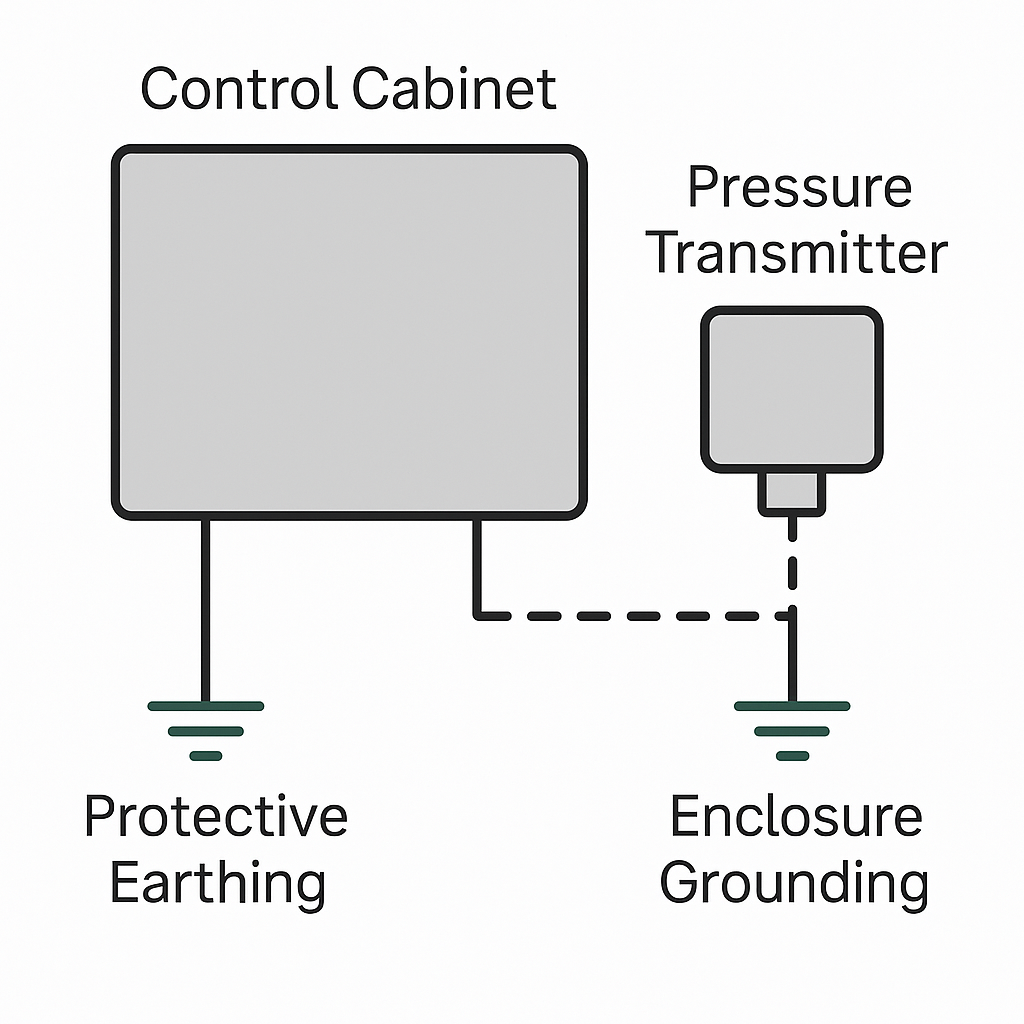
✅ Real-World Example
Imagine a control cabinet that houses a pressure transmitter with a 4–20 mA signal output. The transmitter’s metallic body is grounded for EMC reasons (enclosure grounding), while the cabinet itself is connected to the PE system for safety.
If a fault causes a live wire to touch the transmitter’s casing, only the protective earth system ensures safe disconnection. The EMI grounding alone may not carry fault current safely.
✅ Key Differences at a Glance
| Feature | Protective Earthing (PE) | Enclosure Grounding |
|---|---|---|
| Purpose | Human safety during fault | EMI shielding, functional performance |
| Mandatory | Yes (per safety codes) | No (but recommended) |
| Design Standard | IEC/NEC, safety regulations | IEC 61000-5, EMC guides |
| Grounding Path | Direct to main earth | May go through chassis or signal ground |
| Fault Handling | Yes, trips circuit | No, not intended for fault currents |
✅ Conclusion
Protective earthing and enclosure grounding serve distinct but sometimes overlapping purposes. While both involve connecting components to ground, only protective earthing is designed to prevent electric shock. Enclosure grounding supports system stability and EMI control, and is a part of good engineering practice but not a replacement for PE.
In critical systems, always distinguish their roles and verify grounding paths during design and installation.