Temperature transmitters play a crucial role in industrial automation and instrumentation by accurately converting temperature measurements into standardized electrical signals for monitoring and control. Despite their importance, issues such as a lack of output can arise. In this article, we explore the key components of temperature transmitters, their functions, and provide a detailed troubleshooting guide for diagnosing and resolving output failure problems.
1. Overview of Temperature Transmitter Functions
1.1 Amplification and Signal Processing
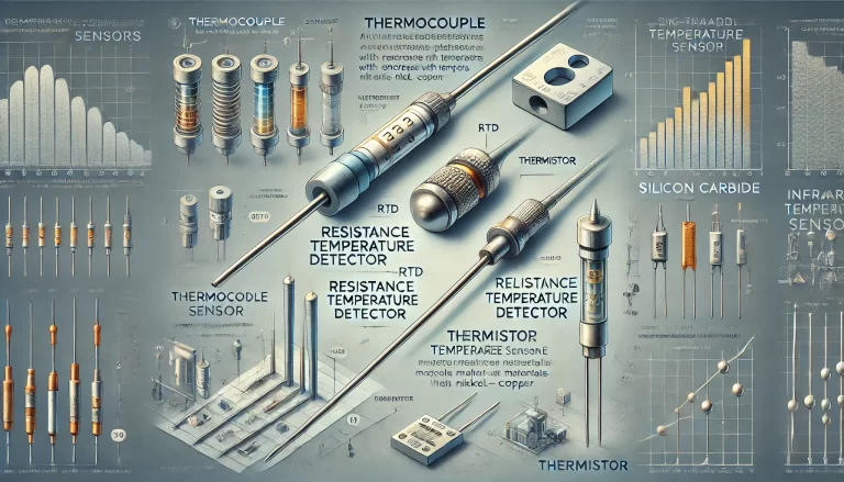
Unlike simple sensors, temperature transmitters not only convert physical quantities (e.g., temperature) into electrical signals but also amplify and process these signals to ensure reliable and precise output. Temperature transmitters typically consist of several key units:
Thermocouple-based Temperature Transmitters:
Reference Source: Ensures a stable baseline for comparison.
Cold Junction Compensation: Corrects errors due to ambient temperature variations at the junction.
Amplification Circuit: Boosts the weak thermoelectric voltage generated by the thermocouple.
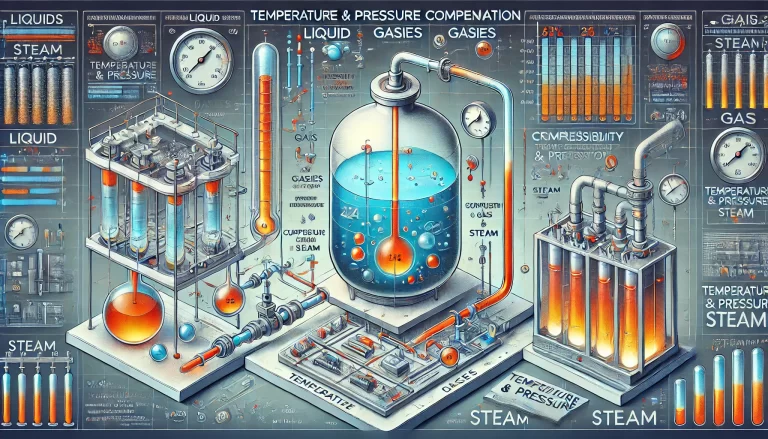
Linearization Circuit: Corrects for non-linearities between the thermoelectric voltage and temperature.
Voltage-to-Current (V/I) Conversion: Converts the processed voltage into a standardized 4-20 mA current output.
Protection Circuits: Include reverse polarity protection, open circuit detection, and current limiting features.
Resistance Temperature Detector (RTD)-based Temperature Transmitters:
Reference Unit: Provides stable electrical parameters.
Resistance-to-Voltage (R/V) Conversion: Converts resistance changes into a measurable voltage.
Linearization and Compensation: Adjusts for non-linear relationships between resistance and temperature.
V/I Conversion: Outputs a 4-20 mA current signal proportional to temperature.
Protective Circuits: Similar to thermocouple-based transmitters.
1.2 Integrated Design
An integrated temperature transmitter combines the sensor (thermocouple or RTD) with the signal processing unit inside a compact enclosure, commonly mounted in the connection head of the sensor assembly. This design improves installation efficiency and reduces wiring complexity.
2. Role of Temperature Transmitters in Measurement Systems
Temperature transmitters convert sensor signals into standard electrical outputs for various applications, including:
Data Acquisition: Inputting signals to display or recording instruments for temperature monitoring.
Automation Systems: Sending signals to controllers for automatic temperature regulation.
Computer Integration: Allowing computers to perform temperature monitoring, control, and data analysis.
However, malfunctions, especially no-output issues, can disrupt these systems. Troubleshooting and preventive maintenance are essential to ensure reliable performance.
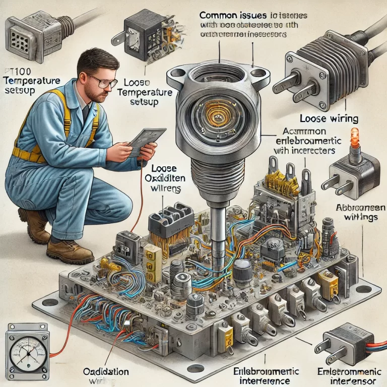
3. Common Causes and Solutions for No Output Issues
3.1 Incorrect Power Supply Connections
Ensure the power supply polarity is correct. Reverse polarity can prevent the transmitter from functioning.
Solution: Verify the positive and negative connections are correctly aligned with the transmitter’s input terminals.
3.2 Insufficient Power Supply Voltage
Check if the power supply voltage meets the transmitter’s requirements. Typically, a 24V DC supply is needed, with a minimum of 12V at the transmitter’s input.
Solution: Measure the supply voltage and ensure it is adequate. Inspect for broken wires, incorrect wiring, or high input impedance on connected devices (which should not exceed 250 Ω).
3.3 Faulty Display or Indicator Module
For transmitters with built-in displays, a damaged indicator may cause the appearance of no output.
Solution: Temporarily short the display module’s input wires. If output resumes, replace the defective display.
3.4 Circuit Issues in the Transmitter
If other components in the system are not the cause, the transmitter circuit itself may be at fault.
Solution: Insert an ammeter in the 24V supply loop to measure the current output. If the output is within the normal range (4-20 mA), the transmitter is likely functioning correctly. Investigate other devices in the circuit.
3.5 Incorrect Wiring
Ensure the power supply wires are connected to the correct input terminals on the transmitter.
Solution: Double-check the wiring connections against the transmitter’s installation manual.
4. Additional Troubleshooting Tips
In real-world applications, various other issues can affect transmitter performance. Sensitive components are difficult to repair and should be replaced by contacting the manufacturer. Users are advised to carefully diagnose issues before installation and operation to minimize downtime.
By understanding the structure, function, and troubleshooting methods for temperature transmitters, users can effectively diagnose and resolve common issues, ensuring stable and reliable operation of industrial processes.