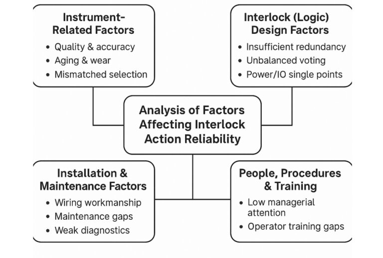
Purpose. This note summarizes why interlock functions may mis-actuate or fail to act, and what to do about it—covering instruments, logic design, installation/maintenance, and people/process.
1) Instrument-Related Factors
Quality & accuracy. Low-cost, mixed-quality instruments degrade stability/accuracy and raise the risk of spurious trips and nuisance alarms when used as interlock initiators.
Aging & wear. Sensing elements and electronics drift and fail over time. Examples: DP transmitters and remote seal level transmitters can suffer from silicone oil aging/leakage; electronics in harsh refinery/petrochemical environments face wide temperature swings, vibration, and corrosive/toxic media that shorten life.
Mismatched selection. Poor fit to service conditions leads to failure modes that propagate into the logic. Example: using an orifice plate on heavy, dirty oil can clog impulse lines; if that flow tag participates in an interlock, it may trigger a false trip.
Mitigations
Specify certified accuracy/stability for safety-related tags; use proven-in-use models.
Apply lifecycle proof-test intervals based on PFD_avg targets.
Select technology for the fluid and fouling risk (e.g., vortex/Coriolis for dirty/heavy fluids; purge/heat-trace impulse lines; remote seals as needed).
2) Interlock (Logic) Design Factors
Insufficient redundancy. Single-sensor trips are vulnerable to any single bad reading or wiring issue, causing spurious trips.
Unbalanced voting. Two sensors where one is faulty can mask demand (refuse-to-trip) or produce indeterminate states.
Power/IO single points. Single power supply or placing redundant channels on the same IO card creates common-cause failure; a supply dip or card fault can force an unintended trip.
Mitigations
Use appropriate voting (1oo2, 2oo3) for hazard rate vs. spurious trip trade-offs; include quality/status in the vote.
Physically separate redundant channels (different cards, marshalling, junction boxes, conduits).
Provide redundant, monitored power and watchdogs; add diagnostic alarms distinct from safety trips.
3) Installation & Maintenance Factors
Wiring workmanship. Damaged insulation, strained cables, poor terminations, or loose screws create intermittent faults and noise pickup that appear as process excursions.
Maintenance gaps. Lack of routine cleaning, calibration, and impulse-line care allows zero drift, plugging, or sluggish response to go unnoticed.
Weak diagnostics. Missing or ignored self-diagnostics means faults are only recognized after a trip or a process upset.
Configure and routinely review device diagnostics; escalate bad-actors to root-cause analysis.
4) People, Procedures & Training
Low managerial attention. Without end-to-end ownership—from design/specification through procurement, installation, and O&M—small gaps compound into major incidents (per Heinrich’s Law).
Operator training gaps. When an interlock fires, operators may not know the initiating conditions, correct reset sequence, or permissive logic—delaying recovery and increasing losses.
Mitigations
Assign lifecycle ownership for each interlock (design → validation → operations → MOC).
Provide targeted training and simulations: initiating conditions, cause & effect, permissives, reset logic, and post-trip checks.
Keep Cause & Effect (C&E) and bypass/reset procedures up-to-date and at the console.
Quick Reference: Common Failure Modes & Countermeasures