1. Overview
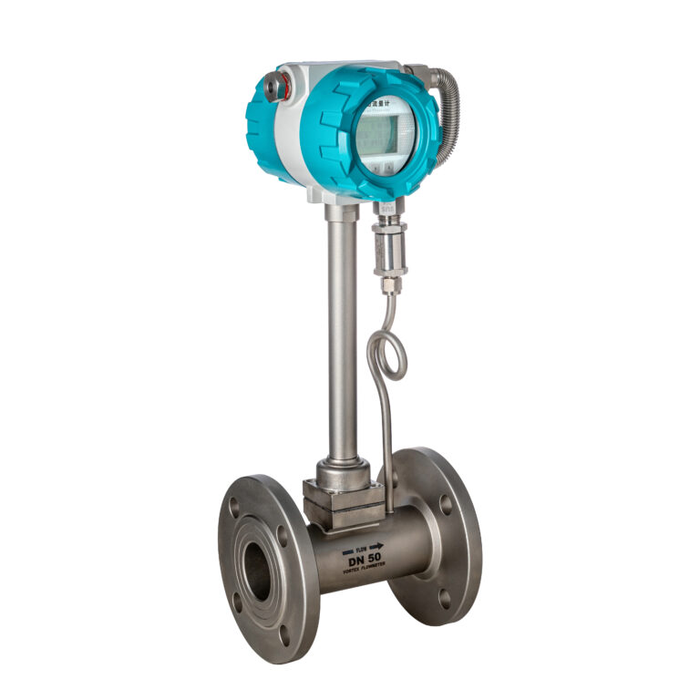
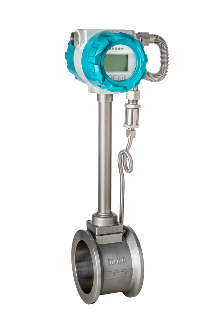
The intelligent vortex flowmeter is mainly used for measuring the flow of fluids in industrial pipelines, including gases, liquids, and steam. Its characteristics include low pressure loss, a wide range, and high accuracy. It is almost unaffected by fluid density, pressure, and temperature parameters when measuring the working volume flow. With no moving mechanical parts, it has high reliability and requires minimal maintenance, ensuring stable instrument parameters over the long term. This instrument uses a piezoelectric stress sensor with high reliability and operates within a temperature range of -25°C to 250°C. It provides both analog standard signals and digital pulse signal outputs, making it easy to integrate with computer digital systems, making it an advanced and ideal flowmeter.
2. Vortex Flowmeter Outputs Signal with No Flow
Signal Output When Power is On and Valve is Closed
- The shielding or grounding of the sensor (or detection element) output signal is poor, introducing external electromagnetic interference.
- The instrument is too close to high-power or high-frequency equipment, resulting in space electromagnetic radiation interference affecting the instrument.
- There is significant vibration in the installation pipeline.
- The converter’s sensitivity is too high, causing excessive sensitivity to interference signals.
Recommended Measures: Improve shielding and grounding, eliminate pipeline vibration, and adjust the converter’s sensitivity to a lower level.
Signal Output When Vortex Flowmeter is in Intermittent Working State
- If the power is not disconnected and the valve is closed, but the output signal does not return to zero, this may be caused by pipeline oscillation and external electromagnetic interference.
Recommended Measures: Lower the converter’s sensitivity and increase the trigger level of the shaping circuit to suppress noise and overcome false triggering during intermittent periods.
No Return to Zero When Downstream Valve is Closed in Powered State
- Closing the upstream valve returns the output to zero, primarily due to the influence of pulsating pressure of the fluid upstream of the vortex flowmeter. If the vortex flowmeter is installed on a T-shaped branch, with pulsating pressure from the main pipeline upstream or if there is a pulsating power source (e.g., piston pump or Roots blower) upstream, it causes false signals.
Solution: Install the downstream valve upstream of the vortex flowmeter and close the upstream valve during shutdown to isolate the pulsating pressure. Ensure sufficient straight pipe length when positioning the upstream valve away from the vortex flowmeter.
3. No Signal Output from Vortex Flowmeter
Possible reasons for this issue include:
- Power disconnection, meaning no power reaches the converter, so it does not work.
- Power lines are connected incorrectly.
- Signal line between the detection element and converter input is disconnected, with no signal reaching the pre-amplifier input.
- Failure of certain converter components (such as amplification circuits, filtering circuits, shaping circuits, or output circuits).
- No or minimal flow in the pipeline.
- Pipeline blockage or the detection element is stuck.
4. Vortex Flowmeter Output (or Display) Signal Does Not Vary with Flow
Possible causes include:
- Poor grounding or improper selection of the signal line’s shielding layer, leading to severe external electromagnetic interference (e.g., 50Hz power frequency interference), which completely suppresses the weak vortex signal, with the output signal drowned out by noise.
- Disconnection between the detection element and converter, open circuit at the pre-amplifier input, or grounding short-circuit of one signal line of the detection element, causing severe common-mode interference, allowing noise to suppress the vortex signal.
- Excessive gain in the pre-amplifier, causing self-oscillation and locking the output at the self-oscillation frequency.
Solution: Improve shielding and grounding, use rational wiring to minimize or eliminate interference, allowing the instrument to resume normal operation.
- Strong pipeline or environmental vibrations, especially if the vibration direction matches the detection element’s sensitive direction, can suppress the vortex signal, resulting in a vibration frequency output signal. Adjusting the valve opening cannot change this output.
Solution: Adopt anti-vibration measures (such as adding pipeline vibration-damping seats and fixing the pipeline). Determine the vibration direction and rotate the vortex flowmeter sensor ±90° around the pipe axis to make the detection element’s sensitive direction perpendicular to the vibration direction, which can reduce vibration impact. Alternatively, slightly lower the pre-amplifier’s gain and trigger sensitivity to eliminate vibration interference.

5. Unstable Vortex Flowmeter Output Signal
Unstable signals primarily manifest as irregular pulse signals in the vortex flowmeter output, with highly inconsistent pulse widths, occasional multiple or missing pulses. Measuring the signal frequency with a frequency meter shows significant fluctuations, with the displayed value varying widely; analog output signal indicators may also vary significantly and be unstable.
Possible Causes:
- Electrical Causes: Electromagnetic interference may overlap with the vortex signal, causing the signal to vary, leading to multiple or missing pulses. Additionally, inappropriate settings for the pre-amplifier’s filtering parameters, gain, and sensitivity adjustments may cause similar issues.
- Detection Element Causes: Contamination or moisture in the detection element reduces sensitivity, weakening the output signal and causing missing pulses. If the sensitivity is too high, minor disturbances outside the main vortex, such as fluid noise, may be detected, causing multiple pulses. Loose or poor contact in the detection element wiring can also cause signal fluctuations.
- Installation Causes: If the measurement tube and piping are misaligned during installation, or if the sealing gasket protrudes into the tube, fluid disturbances may create additional vortices; insufficient straight pipe length upstream and downstream can disturb the vortex’s stability.
- Process Causes: Unstable pipeline flow, large fluctuations in operating parameters, and varying flow rates.

6. Leakage in Measurement Pipeline
Leakage in the measurement pipeline is also a common fault after long-term use, which may be caused by:
- Excessive pressure in the pipeline.
- High temperature of the pipeline fluid or rapid temperature fluctuations causing fastener loosening.
- Seal failure.
- Corrosion of the instrument body or detection element.
