1. Introduction
In recent years, magnetic float level gauges have been widely used in high-pressure separators for solvent oil hydrotreating units. However, issues related to the magnetic float’s deformation and failure have been observed, leading to inaccurate liquid level readings. One such instance occurred in 2012 when the magnetic float in the high-pressure separator V101 of a solvent oil hydrotreating plant became damaged after the unit underwent a technical upgrade, which doubled its production capacity. The damage to the magnetic float caused the level gauge to malfunction, making it impossible to monitor the liquid level accurately. This posed a serious risk to the safety of the plant’s operations. This paper aims to analyze the failure mechanisms of the magnetic float, investigate its structural weaknesses, and propose improvements to enhance the reliability of the magnetic float level gauge in high-pressure environments.

2. Principles, Structure, and Parameters of Magnetic Float Level Gauges
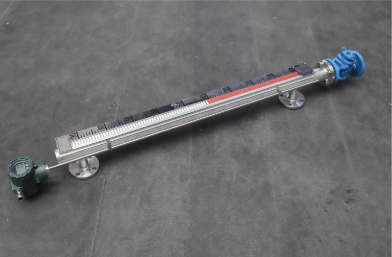
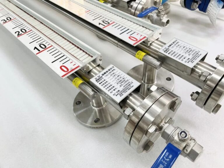
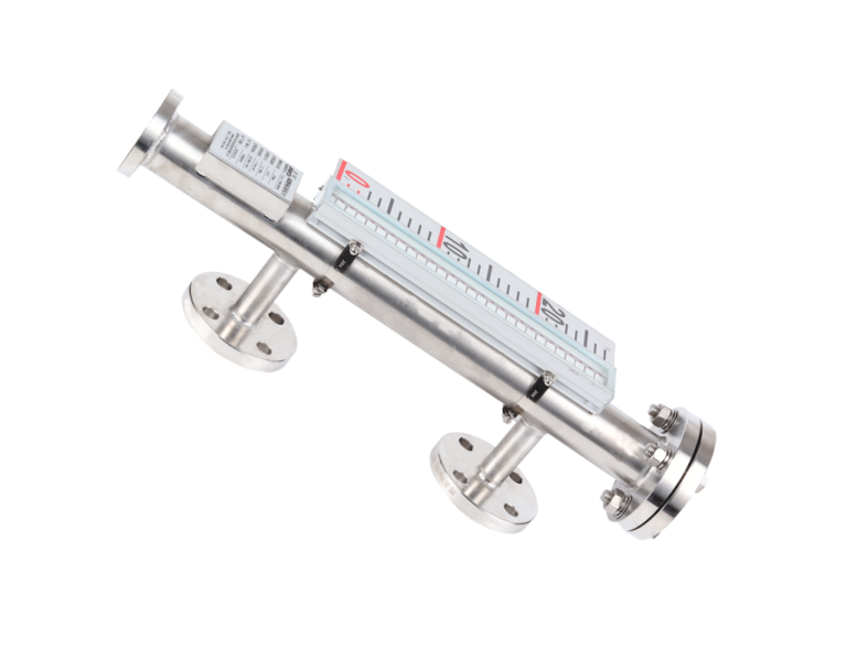
The magnetic float level gauge uses a magnetic float as the sensing element, with the interaction between the float’s magnetic field and the magnetic material in the display strips to indicate the liquid level. The gauge is connected to the vessel being measured, ensuring that the liquid level inside the vessel is reflected in the measurement tube. As the float moves according to the liquid level in the vessel, it activates a magnetic system that changes the color of the display strip—red for liquid presence and white for the absence of liquid. This system provides a clear, local, and accurate indication of the liquid level in real-time.
The main components of the magnetic float level gauge include the measuring tube, float, display panel, connecting flange, vent valve, and others. The float inside the measuring tube moves in response to changes in the liquid level, with the color flip mechanism of the display panel providing the readout.

3. Analysis of Magnetic Float Damage
The magnetic float in the level gauge used in the high-pressure separator is constructed from seven cylindrical sections and two end caps welded together. The point of failure was identified in the third and fourth cylindrical sections, where the float had deformed and ruptured along the weld between the second and third sections (Figure 3.1). The float is a closed cylindrical structure filled with nitrogen gas under pressure.
When a thin-walled cylindrical shell is subjected to external pressure, it can experience sudden deformation, either collapsing or wrinkling. This is particularly problematic when the internal stresses in the shell transition from simple compression to a more complex bending stress. Once the external pressure exceeds the critical pressure, the shell will undergo irreversible deformation. Therefore, it is critical to ensure that the working pressure does not exceed this threshold.
3.1 Detailed Analysis of Magnetic Float Deformation
The deformation of the float is primarily caused by external pressure exceeding the critical pressure that the float’s structure can withstand. To understand this more clearly, we categorized the cylindrical container under external pressure into three types, based on the calculation of critical length. These categories help in determining the suitability of the material and the structural design for high-pressure applications.
The float’s spherical end caps and cylindrical body are made from 1.4 mm thick stainless steel (316), with an outer diameter of 59 mm and a length of 250 mm. The float is filled with nitrogen gas at a pressure of 6.5 MPa and lacks any internal reinforcements such as strengthening rings. This design was originally intended to balance the float’s buoyancy with the liquid level while also ensuring it could withstand the required pressure strength.
However, upon closer examination, it was found that the structural integrity of the float was compromised due to insufficient pressure resistance, causing the deformation and rupture at the welded joints. The failure mechanism was linked to both material properties and the lack of internal reinforcement, which failed to provide adequate support for the pressure conditions.

4. Proposed Improvements for Magnetic Float Structure
Based on the analysis of the failure mechanism, several measures are recommended to improve the magnetic float’s design:
- Increasing Wall Thickness: By increasing the wall thickness of the cylindrical body, the float can better withstand the internal and external pressures without experiencing deformation.
- Reinforcing the Float’s Structure: Incorporating internal reinforcement, such as strengthening rings, could help distribute the pressure more evenly across the surface of the float, preventing localized deformation.
- Material Selection: Using a higher-strength material, or a composite material, would increase the float’s resistance to pressure while reducing the risk of failure.
- Optimizing the Weld Design: Improving the weld design, particularly the joints between the cylindrical sections, would enhance the structural integrity of the float and prevent rupture at these points under high pressure.

5. Conclusion
In conclusion, the failure of the magnetic float in the magnetic float level gauge of the high-pressure separator V101 was primarily caused by structural weaknesses and an inability to withstand high external pressure. The proposed modifications—such as increasing the float’s wall thickness, adding internal reinforcements, and optimizing the material—will not only enhance the float’s pressure resistance but also reduce the production costs by simplifying the manufacturing process. These improvements will contribute to the safe, stable, and reliable operation of the level gauge, ensuring more accurate liquid level monitoring and improving the safety of the plant’s operations.
