
Many people assume that the neutral wire is simply a “wire with no electricity.” In industrial electrical systems, however, this misunderstanding can easily lead to incorrect troubleshooting and even safety hazards.
Power distribution cabinets, control panels, variable frequency drives (VFDs), UPS systems, lighting circuits, PLCs, and industrial instruments all rely on conductors such as L, N, and PE. Their differences are not just in their names—they serve completely different purposes within the electrical system.
This article explains what each conductor actually does, where it comes from, and why confusing them can cause serious problems.
1. Live Wire (L) – The Conductor That Supplies Power
The Live Wire, also called the Phase Wire, is identified by L. In three-phase systems, it is typically labeled L1, L2, and L3.
In a typical low-voltage three-phase four-wire system, the live conductors originate from the phase terminals of the transformer secondary winding.
Typical voltages are:
- 220–230 V between Live (L) and Neutral (N)
- 380–400 V between phases (L-L)
The live conductor delivers electrical energy to loads such as:
- Electric motors
- Contactors
- Variable Frequency Drives (VFDs)
- Servo drives
- Electric heaters
- Lighting systems
- Control panels
Without the live conductor, electrical equipment cannot operate.

2. Neutral Wire (N) – The Return Path of the Working Circuit
The Neutral Wire is identified by the letter N, which stands for Neutral.
In a three-phase four-wire system, the transformer or generator winding is commonly connected in a star (wye) configuration. The conductor connected to the star point is called the Neutral Wire.
The neutral conductor serves two important functions:
- It completes the electrical circuit for single-phase loads.
- It carries the unbalanced current of a three-phase system.
Industrial facilities often have numerous single-phase devices connected to the neutral conductor, including:
- PLC power supplies
- Instrument power supplies
- Switching power supplies
- Lighting systems
- Socket outlets
When many electronic devices with rectifier inputs operate simultaneously, third-order harmonics and their multiples accumulate on the neutral conductor. As a result, the neutral current may become significantly higher than expected, causing:
- Neutral busbar overheating
- Hot terminals
- Insulation deterioration
3. “Neutral Wire” (Common Name) – Why It Can Be Misleading
In everyday language, many people refer to the Neutral Wire (N) simply as the “neutral wire” or “zero wire.”
However, in industrial electrical engineering, the correct term is Neutral (N).
The traditional name originated because the transformer neutral point is grounded, making the conductor’s voltage close to earth potential under normal operating conditions.
But “close to zero voltage” does NOT mean “safe.”
The neutral conductor is part of the working circuit and normally carries current.
If any of the following occurs:
- Neutral conductor breaks
- Loose connections
- Severe load imbalance
its voltage may rise significantly, creating an electrical shock hazard.
For engineering drawings, electrical cabinets, and maintenance documentation, conductors should always be identified as L, N, PE, or PEN, rather than using informal names.
4. Protective Earth (PE) – The Safety Conductor
The Protective Earth (PE) conductor is used exclusively for electrical safety.
PE connects exposed conductive parts such as:
- Equipment enclosures
- Electrical cabinets
- Cable trays
- Metal conduits
- Structural steel
- Equipment frames
to the grounding system.
Its primary purpose is to provide:
- A fault current path
- Equipotential bonding
- Personnel protection
If insulation fails and a live conductor touches a metal enclosure, the PE conductor allows fault current to flow safely back to the source or grounding system, enabling:
- Circuit breakers
- Fuses
- Residual Current Devices (RCDs)
to disconnect the fault quickly.
Without a reliable PE conductor, the equipment enclosure may remain energized and become dangerous to anyone touching it.
Unlike the Neutral conductor, PE does not carry operating current under normal conditions.

5. Key Differences Between L, N, and PE
| Item | Live (L) | Neutral (N) | Protective Earth (PE) |
|---|---|---|---|
| Source | Transformer phase | Transformer neutral point | Grounding system |
| Function | Supplies electrical power | Completes the working circuit | Provides electrical protection |
| Carries operating current | Yes | Yes | No (under normal conditions) |
| Typical designation | L, L1, L2, L3 | N | PE |
| Main risks | Electric shock, short circuit | Neutral displacement, overheating | Loss of fault protection |
6. The Relationship Between N, PE, and PEN
The three conductors have different purposes:
- N (Neutral): Working conductor carrying return current.
- PE (Protective Earth): Safety conductor for fault protection.
- PEN: A combined conductor serving both Neutral and Protective Earth functions.
Different grounding systems use them differently.
TN-S System
Neutral (N) and Protective Earth (PE) remain completely separate throughout the installation.
Single-phase loads connect to N, while equipment enclosures connect only to PE.
TN-C-S System
A combined PEN conductor is separated into N and PE at a designated point.
Once separated, N and PE must never be reconnected downstream.
Improper reconnection can result in:
- RCD nuisance tripping
- Touch voltage on equipment enclosures
- Electrical noise
- Communication failures
TT System
Equipment enclosures connect to a local grounding electrode.
Fault protection depends heavily on residual current devices (RCDs), making proper grounding resistance especially important.
IT System
The power source is isolated from earth or connected through a high impedance.
IT systems are widely used in applications requiring uninterrupted power supply, where insulation monitoring devices play a critical role.
7. Common Problems Found in Industrial Electrical Systems
Typical field issues include:
- Loose neutral terminals causing overheating
- Open neutral conductors resulting in neutral point shift and abnormal voltage
- Poor neutral busbar connections causing unstable PLC and instrument power supplies
- Incorrect N-PE bonding leading to nuisance RCD trips and electrical interference
- Loose PE connections preventing proper fault protection
- High grounding resistance reducing fault current capability
- Missing bonding jumpers on cable trays affecting equipotential bonding
- Multiple circuits sharing one neutral conductor, creating dangerous back-feed currents during maintenance
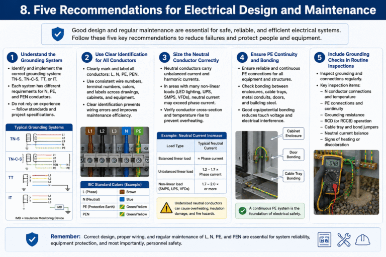
8. Five Recommendations for Electrical Design and Maintenance
To improve both safety and system reliability:
- Understand the grounding system (TN-S, TN-C-S, TT, or IT) before wiring.
- Use clear conductor identification for L, N, PE, and PEN throughout drawings and equipment.
- Size neutral conductors correctly, especially in installations with large numbers of nonlinear loads such as UPS systems, LED lighting, and switching power supplies.
- Verify PE continuity to ensure reliable equipotential bonding across cabinets, equipment, cable trays, and metal structures.
- Include grounding inspections in routine maintenance by checking terminal temperatures, grounding resistance, PE continuity, and RCD operation.
Conclusion
Each conductor has a unique purpose in an electrical system:
- Live (L) supplies electrical power.
- Neutral (N) completes the working circuit.
- Protective Earth (PE) provides fault protection.
- PEN combines the functions of N and PE in specific grounding systems.
Although the Neutral conductor is often informally called the “neutral wire” or “zero wire,” it should never be assumed to be electrically safe simply because its voltage is close to earth potential.
Understanding the differences between L, N, PE, and PEN is fundamental to safe electrical design, proper installation, effective troubleshooting, and reliable industrial operation.