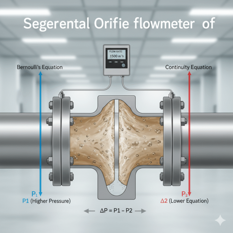
Orifice flow meters are widely used for measuring the flow rate of gases, steam, and liquids in industrial processes. However, when measuring compressible fluids such as gas and steam, the flow measurement accuracy can be significantly affected by changes in operating temperature and pressure.
The reason is that the density of a compressible fluid changes with temperature and pressure variations:
When pressure increases, gas density increases.
When temperature increases, gas density decreases.
Therefore, to obtain accurate flow measurement results under actual operating conditions, temperature and pressure compensation is required.
This article explains the principle of temperature and pressure compensation for differential pressure (DP) flow meters, including orifice plates and averaging pitot tube flow meters, and provides practical implementation methods in PLC/DCS systems.
1. Principle of Temperature and Pressure Compensation
The flow calculation of an orifice flow meter is usually based on a specific design condition, including:
Design pressure
Design temperature
Reference density
However, actual operating conditions are rarely constant. The process pressure and temperature continuously fluctuate, causing changes in fluid density.
For compressible fluids, the relationship between density, pressure, and temperature follows the ideal gas law:
Where:
ρ = Fluid density
P = Absolute pressure
T = Absolute temperature
R = Gas constant
Therefore, the actual flow rate must be corrected according to the real-time pressure and temperature values.
The compensation calculation normally requires:
Flow signal
Pressure signal
Temperature signal
These signals are sent to the DCS or PLC system, where the compensation calculation is performed and the corrected standard flow value is displayed.
2. Temperature and Pressure Compensation System Architecture
Reference conditions from the orifice calculation sheet.
6. Absolute Pressure and Absolute Temperature Conversion
Temperature and pressure compensation must use absolute values.
Pressure Conversion
The relationship is:
Example:
Gauge pressure:
0.5 MPa
Atmospheric pressure:
0.101325 MPa
Absolute pressure:
0.601325 MPa
Temperature Conversion
The relationship is:
Example:
Operating temperature:
200℃
Absolute temperature:
473.15 K
The value 273.15 is a fixed physical conversion constant and does not change with location.
7. Steam Flow Compensation Considerations
For steam measurement, temperature and pressure compensation is especially important.
Applications include:
Boiler steam
Superheated steam
Saturated steam
Process steam
For saturated steam:
Pressure is the main compensation parameter because steam temperature is related to pressure.
For superheated steam:
Both pressure and temperature must be measured and compensated.
Common equipment configuration:
Orifice plate
Differential pressure transmitter
Pressure transmitter
Temperature transmitter
Flow computer / PLC / DCS
8. Common Field Errors During Compensation
1. Double Square Root Calculation
A common mistake:
DP transmitter already outputs flow signal
PLC performs square root again
Result:
Incorrect low flow indication.
2. Incorrect Pressure Unit
Example:
Using gauge pressure directly instead of absolute pressure.
Wrong:
P = 0.5 MPa
Correct:
P = 0.5 + 0.101325 MPa
3. Using Celsius Instead of Kelvin
Wrong:
Temperature = 200
Correct:
Temperature = 200 + 273.15
Conclusion
Temperature and pressure compensation is essential for accurate measurement of gases and steam using orifice flow meters and other differential pressure flow meters.
A reliable compensation system requires:
Correct differential pressure measurement
Accurate pressure and temperature signals
Proper square root calculation
Correct conversion to absolute pressure and Kelvin temperature
Proper PLC/DCS programming
By implementing correct compensation logic, industrial users can significantly improve flow measurement accuracy and ensure reliable process control.