Even when equipment isn’t broken and the program shows no errors, sometimes screens display jumping values; valves won’t open, pumps won’t stop, and sensor signals are intermittent. After checking the control panel for hours, the problem may turn out to be as simple as a loose wire, improper shielding, or a misconfigured 4–20 mA range.
For engineers new to the field, it’s common to focus on PLC programs, HMI screens, or VFD parameters. But real-world experience shows that system stability starts with reliable signals. Temperature, pressure, flow, and level rely on input signals; pumps, valves, motors, and cylinders rely on output signals; alarms, interlocks, and communications—all are supported by signals. If the signals are unreliable, even the best program can’t save the system.
Let’s go through the most common signal types and their key points.
1. Analog Signals
Analog signals vary continuously over time and are used to record temperature, pressure, flow, and level.
Example: tank level rising from 20% to 50%, or pipe pressure increasing from 0.2 MPa to 0.8 MPa.
Transmission methods:
- Voltage signal (0–10 V): Simple and intuitive, suitable for short distances or small devices. Weakness: sensitive to interference and voltage drops over long cables.
- Current signal (4–20 mA): More robust and widely used. The 4 mA “live zero” allows the system to detect wire breaks or power loss (0 mA indicates a fault, not zero measurement). Common for pressure, level, and temperature transmitters.
Key takeaway: analog signals are foundational; ensure correct range, proper grounding, and shielding.
2. Digital Signals
Digital signals have only two states: on/off, yes/no, running/stopped. Examples: pushbuttons, pump status, valve position, proximity sensors.
- Digital Input: tells the PLC what’s happening in the field.
- Digital Output: tells devices to start, stop, or trigger alarms.
Inspection tips: don’t rely solely on the HMI. Check terminal blocks, module LEDs, relay coils, and supply voltage. Often, issues attributed to “wrong program” are actually missing signals.
3. Pulse Signals
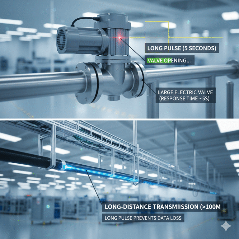
Pulse signals are rhythmic on/off sequences, used for counting, speed measurement, positioning, and timing. They convey information via pulse quantity, frequency, or width.
- Frequency-based signals: determine motion speed or position (e.g., encoders on motor shafts).
- Pulse Width Modulation (PWM): controls devices by varying “on” time ratio—commonly used for motor speed, heating, or dimming.
Note: pulse signals are sensitive to wiring, shielding, and module response. Troubleshooting requires checking cables, grounding, and interference—not just software.
4. Switch / Interlock Signals
Discrete signals used for safety and interlocks. Examples: limit switches, E-stop buttons, safety doors, pressure switches, and level switches.
- Provide simple results: open/closed, within limit/exceeding limit.
- Example: if a safety door opens, the machine must stop; if pressure exceeds limit, output must be cut.
Key point: interlock signals are critical for safe operation.
5. Bus Communication
Bus signals enable communication among multiple devices using specific protocols. They allow sensors, controllers, actuators, instruments, VFDs, remote I/O, and PLCs to exchange data and commands in an organized way.
- Fieldbuses: Modbus, Profibus, DeviceNet
- Industrial Ethernet: Profinet, EtherNet/IP
Advantages: fewer wires, improved expandability, and access to richer diagnostic data.
Example: a VFD using hard-wired signals would need separate cables for start/stop, fault, run feedback, frequency setpoint, and feedback. Using a bus reduces wiring and increases monitoring capabilities.

6. Optical Signals
Optical signals are non-contact detection methods. Common applications: conveyor product detection, bottle positioning on packaging lines, robotic grasp verification.
- Advantages: non-contact, fast response, flexible installation.
- Limitations: sensitive to dust, oil, strong reflections, or misalignment.
Tip: clean the sensor lens; sometimes a simple wipe resolves intermittent errors.
7. Wireless Signals
With Industrial IoT, wireless signals are increasingly used: Wi-Fi, Bluetooth, Zigbee, LoRa, NB-IoT.
- Ideal for remote monitoring, dispersed data collection, or mobile devices.
- Suited for low-frequency, non-critical control. Critical safety or real-time control should not rely solely on wireless.
8. Signal Conversion
Signals often require processing before reaching controllers:
- Signal conditioning: filters, isolation, amplification for analog signals.
- ADC (Analog-to-Digital Conversion): converts analog signals to digital for PLC, DCS, or microcontroller use.
- DAC (Digital-to-Analog Conversion): converts digital control results into analog signals to control valves, VFDs, or actuators.
Key: check the whole chain—not just the sensor. Longer chains require step-by-step verification.

9. Troubleshooting Checklist
| Signal Type | Key Checks |
|---|---|
| Analog | Range, grounding, shielding, interference |
| Digital | Contacts, voltage, common terminal |
| Pulse | Frequency, cabling, response speed |
| Bus | Protocol, address, network status |
| Optical | Installation, contamination, reflections |
| Wireless | Environment, distance, stability |
Final takeaway: automation is essentially devices “talking” to each other. Signals are their language. Stable signals = stable control; accurate signals = accurate system. Reliable automation is not just about writing programs—it’s about knowing, monitoring, and managing every signal on site.