The instrument calibration process must strictly follow the “Metrology Calibration Regulations” (e.g., JJG882-2019) and the technical requirements of the equipment. Based on industrial field operations, the process can be broken down into six key stages. Each stage includes clear operational points and data recording requirements. The detailed process is as follows:
1. Preparation Phase (Pre-calibration Requirements)
This phase focuses on ensuring that all conditions—personnel, equipment, materials, methods, and environment—meet the calibration requirements to avoid invalid results due to insufficient preparation.
Equipment and Tool Preparation:
Verify the instrument’s basic information, such as model, range, and accuracy (e.g., the 4# Furnace Pressure Transmitter 7MF0300-1WE01-5AF-Z, range 0–25 MPa, accuracy 0.075).
Check for any visible damage, loose terminals, etc.
Select standard instruments with an accuracy level ≥3–10 times the instrument to be calibrated (e.g., CONST-273 Intelligent Pressure Calibrator, accuracy 0.05).
Ensure the validity of the metrology certificate of the standard instrument (e.g., valid until 2026.05.17).
Prepare auxiliary tools like terminal blocks, insulation resistance meters, pressure testing tools (e.g., pressure pumps), and calibration forms.
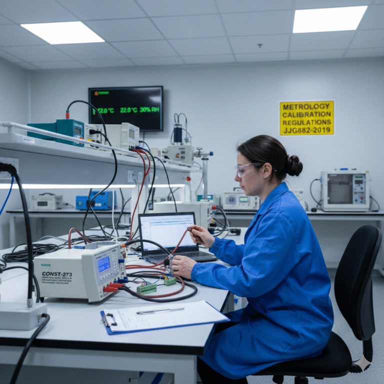
Environmental Control:
Adjust temperature and humidity according to regulations (e.g., for pressure transmitter calibration, temperature should be (20 ± 5)°C and relative humidity 40–60% RH, e.g., 22°C and 30% RH).
Ensure minimal dust and vibration interference (avoid areas near fans or pumps).
Personnel and Regulations:
Calibration personnel should hold a registered metrologist certificate or relevant training certification and be familiar with the instrument’s principles (e.g., Siemens 7MF series transmitters).
2. Initial Inspection (Eliminate Instrument Faults)
Before calibration, perform basic checks to ensure the instrument is free from inherent faults, preventing distorted calibration data.
Visual and Identification Inspection:
Verify that the nameplate (model, range, serial number) is clear and complete, and check for corrosion, deformation, or other damage.
Ensure that the display is legible and the buttons operate normally.
Electrical Performance Testing:
Insulation Resistance Test: Use a 500V insulation resistance meter to measure the insulation resistance between the “power terminal – outer casing” and “signal terminal – outer casing,” which should be ≥100 MΩ (e.g., 500 MΩ, acceptable).
Sealing Test (for pressure instruments): Apply full-scale pressure (e.g., 25 MPa) for 10 minutes and check for no pressure drop (no leaks).
Zero Point Pre-check:
Apply the rated power supply (e.g., 24VDC) and input the “zero signal” (e.g., 0 MPa), then record the initial output (e.g., 4.004 mA). If the deviation exceeds 50% of the allowable error, troubleshoot wiring or power supply issues.
3. Core Calibration Operations (Linearity and Error Verification)
This phase is the core of the calibration process. Perform tests in the sequence: zero point → range → multi-point linearity, recording both “ascending” (from low to high input) and “descending” (from high to low input) data for error calculation.
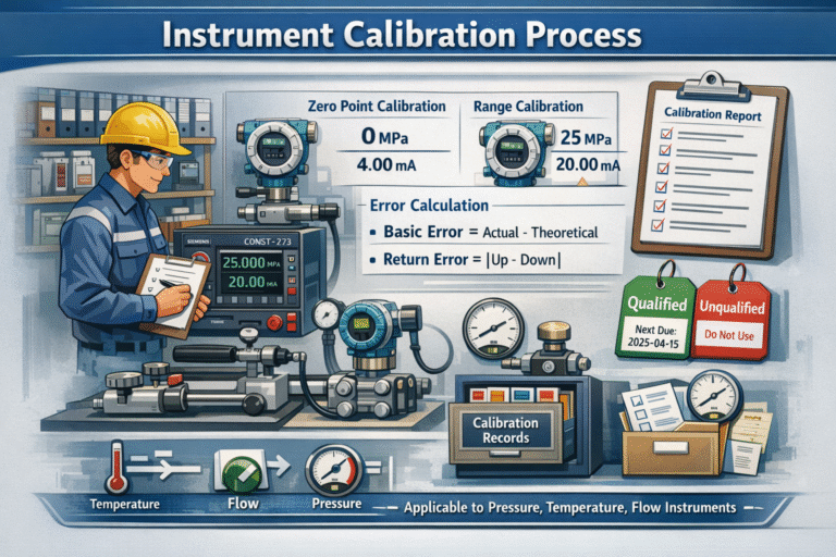
Zero Point Calibration:
Input the “zero signal” (e.g., 0 MPa), wait for stabilization (usually 3–5 minutes), and record the actual output value. If the deviation exceeds one-third of the allowable error (e.g., ±0.4 mA for ±1.2 mA error), adjust the zero point using the instrument’s calibration button or software (e.g., Siemens HART handheld device).
Range Calibration:
Input the “full-scale signal” (e.g., 25 MPa), wait for stabilization, and record the actual output (e.g., 20.000 mA). If the deviation exceeds the allowable error (e.g., 21.3 mA, exceeding ±1.2 mA), adjust the range potentiometer or correct using the handheld device until the output matches the theoretical value (20 mA).
Multi-point Linearity Calibration (mandatory):
Ascending: Gradually increase the pressure from zero (0 MPa) to various calibration points, recording the actual output value at each point (e.g., at 6.25 MPa, the output should be 7.999 mA).
Descending: Gradually decrease the pressure from full scale (25 MPa) to various points, recording the output at each point (e.g., at 6.25 MPa, the output should be 8.002 mA).
Select calibration points at 20%, 40%, 60%, 80%, and 100% of the full scale, ensuring each point is tested in both ascending and descending directions. Each calibration point should be stable for at least 2 minutes.
4. Data Processing and Error Calculation (Compliance Determination)
Based on the recorded “theoretical output values” and “actual ascending/descending outputs,” calculate the basic error and return error to determine compliance with accuracy requirements.
Basic Error Calculation:
Basic error = Actual output value – Theoretical output value (e.g., at 6.25 MPa, the theoretical output is 8 mA, actual output is 7.999 mA, basic error = 7.999 – 8 = -0.001 mA, which is within the allowable error of ±1.2 mA).
Return Error Calculation:
Return error = |Actual ascending output – Actual descending output| (e.g., at 6.25 MPa, ascending output is 7.999 mA, descending output is 8.002 mA, return error = |7.999 – 8.002| = 0.003 mA, which is acceptable if the return error is ≤ half of the allowable error).
Compliance Determination:
If the basic error for all calibration points is ≤ the instrument’s allowable error, and the return error is also within the limit, and insulation resistance and sealing tests pass, the instrument is considered “qualified.”
5. Post-calibration Adjustment and Restoration (If Unqualified)
If the instrument is calibrated correctly, proceed to the next steps; if not, perform adjustments and re-test the key calibration points.
Minor Deviations:
Attempt repairs (e.g., replace seals, clean sensors), then re-calibrate the instrument. Repeat until it meets the acceptable error range.
Severe Deviations:
If repairs do not resolve the issue (e.g., basic error exceeds the allowable range), label the instrument as “unqualified” and send it for repair or disposal.
6. Finalization and Archiving (Compliance Documentation)
Restore the connections between the standard instrument and the calibrated instrument, and reconnect the instrument’s field wiring (e.g., signal lines to the DCS system).
Apply a calibration tag to the instrument, indicating the calibration date and validity period (usually 1 year).
Complete the calibration record form, including equipment information, standard instrument details, environmental data, original calibration data, error calculations, and conclusions. The record should be signed by the calibrator, reviewer, and approver, and archived in the company’s metrology management archive for at least three years.

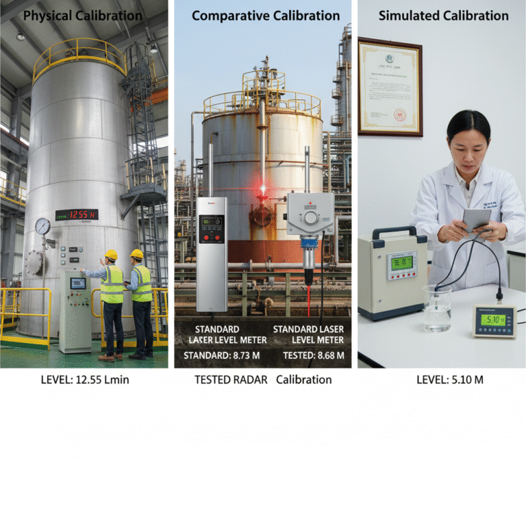
This process can be applied directly to the calibration of various industrial instruments such as pressure, temperature, and flow meters. Different instruments only require adjustments in the “type of standard instrument” (e.g., a temperature transmitter would use a standard thermostatic bath) and “calibration point selection rules” (e.g., for flow meters, calibration points are selected at 10%, 30%, 50%, 70%, and 100% of the full range). The core logic remains consistent across different instruments.