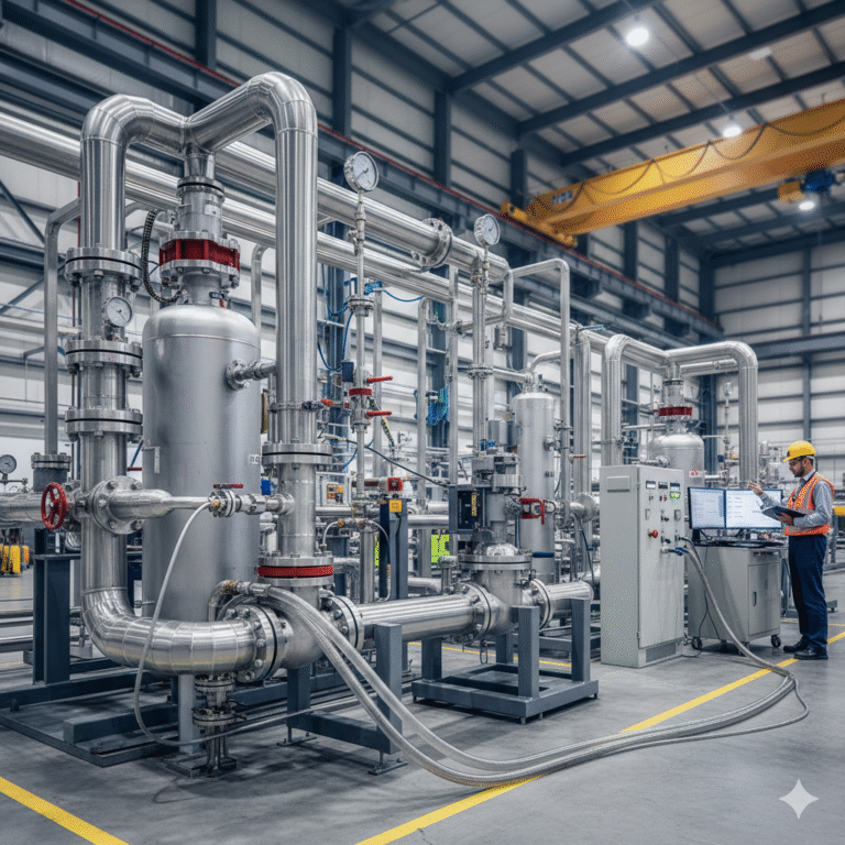
In industries dealing with pressure vessels, process pipelines, heat exchangers, valves, and other equipment, pressure testing is an unavoidable part of equipment delivery, system commissioning, and project acceptance. However, behind this highly standardized process, the true engineering purpose, risk boundaries, and the relationship between pressure testing and design assumptions are often reduced to a routine task: “Increase the pressure, and as long as there are no leaks, it’s good to go.” In fact, this is a very dangerous and common misunderstanding.
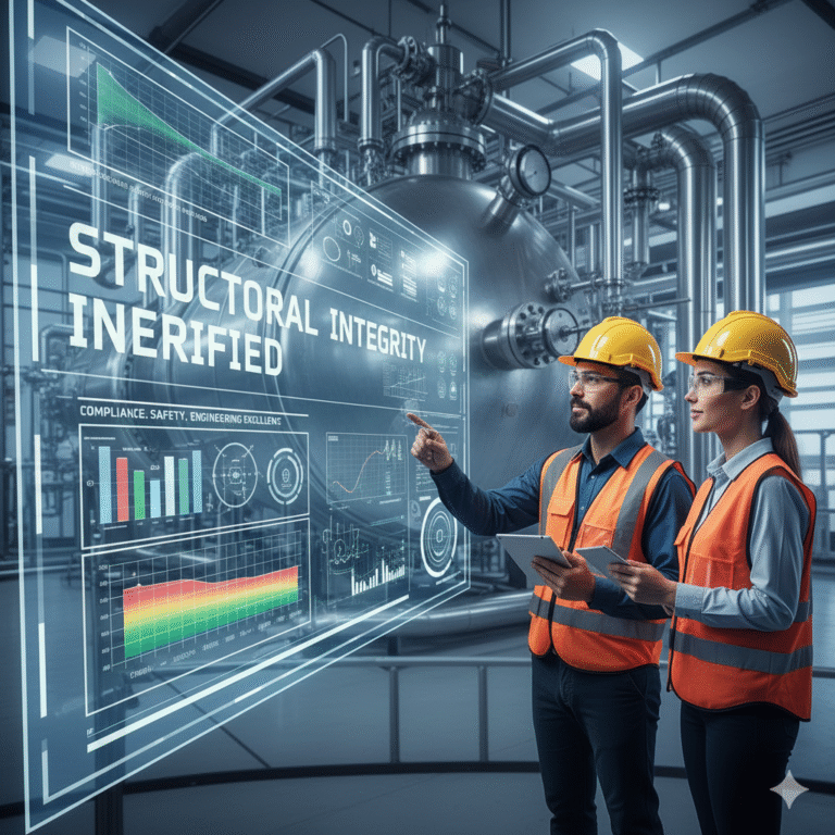
Pressure testing, as defined in mainstream technical standards like ASME, GB, and EN, has never been regarded as merely a leak-checking or procedural test. Rather, it is a structural integrity verification method with clear engineering boundaries and risk control objectives. Understanding the technical connotations of pressure testing is an essential prerequisite for engineers to make sound technical judgments during design, manufacturing, installation, and acceptance stages.
1. Pressure Testing: Verifying Structural Safety
In the context of industrial equipment, pressure testing is not a mere pressure-checking operation. It is an engineering test that, under controlled overload conditions as specified by standards, verifies whether pressure-containing equipment has sufficient structural safety margin, based on the design assumptions and material strength models. Regardless of the specific standard (ASME BPVC, China’s GB150 series, or the European EN/PED system), pressure testing is clearly classified as part of structural safety verification. Its focus is on the equipment’s overall load-bearing capacity and structural integrity, not on performance under operating conditions or sealing functions.

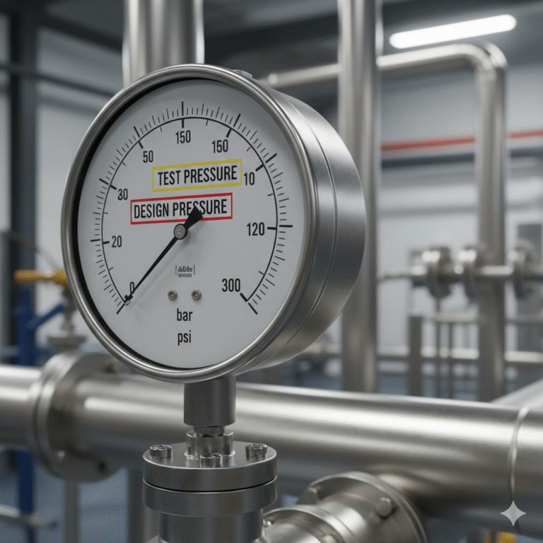
2. Design Pressure vs. Test Pressure: The Standard Logic
Many engineers wonder: “If the equipment is already designed based on the design pressure, why do we need to test it at 1.25 to 1.5 times that pressure?” The answer is simple: design pressure is based on assumptions, while test pressure reflects reality.
Design Pressure: Although different standards may define it slightly differently, the engineering meaning remains consistent. It represents the maximum internal pressure that the equipment is designed to withstand under the most adverse conditions, not its physical limit. For example, in ASME BPVC, design pressure is used to determine minimum wall thickness and stress calculations. In GB150 and GB/T 20801, it similarly serves the purpose of strength calculation and structural design.
Test Pressure: This is an important control parameter used to verify if the design assumptions hold. In ASME BPVC Section VIII, the water pressure test pressure is typically no less than 1.3 times the design pressure, adjusted for temperature. In GB and EN standards, this range is generally 1.25 to 1.5 times the design pressure. The test pressure coefficient is not derived from a single mechanical formula, but rather an engineering result formed through the statistical distribution of material yield strength, manufacturing and welding defect probabilities, and experience with long-term engineering accidents. The goal of pressure testing is not to approach the structural strength limit but to confirm that the equipment remains within elastic operation without irreversible damage after depressurization.
3. Internal Pressure vs. Structural Stress
Internal pressure itself does not directly lead to equipment failure; what determines structural safety is the stress state formed after pressure is transferred through the geometry and material properties. Despite differences in calculation methods, all major standards are based on elastic mechanics assumptions and allow for stress design concepts. In engineering practice, failure risks often concentrate in areas where material continuity is interrupted, such as welds (especially longitudinal seams), transitions between nozzles and shells, flanges, reinforcement structures, temporary closures, and blind flanges. These areas often have uneven material properties, geometric discontinuities, stress concentrations, and redistributed load paths, making it difficult to fully reflect the true stress state through simplified calculations. Pressure testing, by applying pressure to the entire system, exposes these potential weak points to real operating conditions, allowing for a comprehensive verification of design, manufacturing, and installation quality.

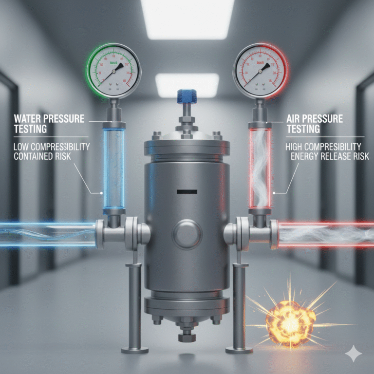
4. Water vs. Air Pressure Testing: Risk Classification
Water pressure testing is the preferred method in most standard systems due to the physical properties of the medium. Water has very low compressibility, meaning it doesn’t store elastic potential energy during pressurization. Even if local failure occurs, the consequences are usually leakage or local structural damage, making the risks relatively controllable.
In contrast, air pressure testing is considered a high-risk operation due to the high compressibility of gases. As pressure increases, significant elastic potential energy accumulates. If the system boundary fails, the result can be a sudden release of energy, significantly amplifying the risk. Therefore, ASME, GB, and EN standards treat air pressure testing as a high-risk operation, only allowing it when necessary, and after taking strict protective measures and conducting a risk assessment.
5. Pressure Testing vs. Sealing Tests
Pressure testing and sealing performance verification are distinct processes in the standards system. Pressure testing verifies the initial structural safety and the quality of manufacturing and installation, with the qualification criteria focusing on structural integrity, permanent deformation, and load-bearing capacity. It does not require absolute zero leakage under all test pressures.
Sealing performance, on the other hand, is usually evaluated through separate leak tests, which have different test pressures, criteria, and objectives from pressure testing. Confusing pressure testing with leak testing blurs the engineering goals of the two tests, potentially leading to misinterpretation of results and incorrect decisions.
6. Gradual Pressure Increase and Steady Pressure: Risk Control Strategy
The gradual increase in pressure and steady pressure observation are not merely formalities but are clear risk control strategies outlined in standards. Gradual loading allows defects to be exposed at lower energy levels, preventing brittle failure from sudden overloading. The steady pressure phase allows the structure to complete stress redistribution under constant load, revealing potential issues.
7. Boundaries of Pressure Testing Capability
All major standards clearly define the scope of pressure testing. It can verify the overall structural safety of equipment under specific conditions but cannot evaluate long-term fatigue damage, corrosion thinning, or crack propagation during service. Therefore, pressure testing must be combined with non-destructive testing, material assessment, and in-service monitoring to form a comprehensive engineering safety system.
From a standards-setting perspective, pressure testing does not prove the “lifetime safety” of the equipment but rather confirms that it complies with design assumptions at the point of delivery or key milestones.
8. Conclusion
Although ASME, GB, and EN standards may vary in their wording and technical details, they share a strong engineering consensus on pressure testing: through controllable, low-risk overload conditions, they verify whether pressure-containing structures have sufficient safety margins under real-world conditions. True professional engineers are never satisfied with merely meeting “what the standards require”; they seek to understand why the standards are written as they are and whether the test results align with the expected structural behavior.