From Vessel Rupture to Weld Failure and Flange Leakage
In real engineering practice, ASME is rarely discussed in philosophical terms.
Most engineers encounter it in a much more concrete — and often frustrating — way:
Required wall thickness suddenly increases
Additional radiographic testing is requested
Flange ratings must be reselected
Documents are rejected and returned for revision
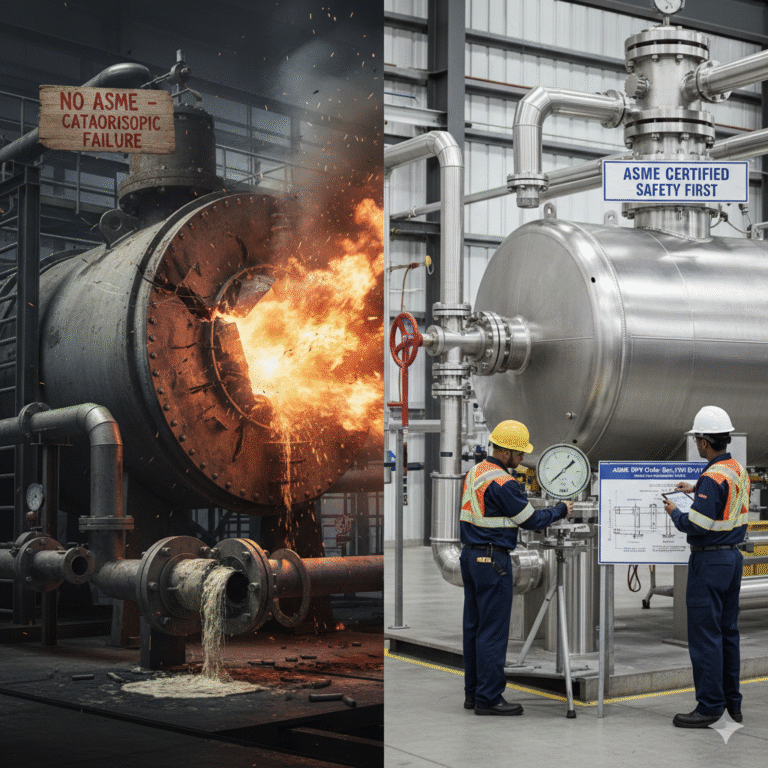
ASME (American Society of Mechanical Engineers) standards mainly apply to pressure-containing equipment, such as boilers, pressure vessels, and pressure piping systems.
These systems share one critical characteristic:
when they fail, the consequence is not routine maintenance — it is a high-energy release accident.
ASME does not attempt to ensure that equipment will never fail.
Its true purpose is far more specific:
To prevent sudden, uncontrollable, and catastrophic failures.
1. ASME Principles Are Embedded in Parameters, Not Slogans
ASME rarely talks about safety in abstract language.
Instead, its philosophy is embedded directly in design formulas, allowable limits, and verification requirements.
Across different codes and sections, several consistent principles emerge:
Design is not based on ideal material properties
Weak points are penalized or subjected to higher verification
Local imperfections are tolerated — global loss of control is not
These principles are not theoretical; they are explicitly reflected in ASME clauses and calculations.
2. Allowable Stress: Designing Against Rupture, Not Strength
In ASME BPVC Section VIII, Division 1, pressure vessels are designed using the allowable stress method
(This discussion focuses on Div. 1; Div. 2 and Div. 3 follow different design philosophies.)
Allowable stress is not the material’s ultimate capacity.
It is the maximum stress permitted in design, intentionally set far below failure limits.
For typical carbon steels, ASME defines allowable stress as the lower of:
Tensile strength ÷ 3.5
Yield strength ÷ 1.5 (≈ 2/3 of yield)
These ratios are not the result of precise theoretical derivation —
they are experience-based safety factors developed through decades of failures and investigations.
The underlying assumptions are clear:
Material properties vary
Manufacturing and welding are imperfect
Actual operating conditions often deviate from design assumptions
ASME deliberately chooses conservatism at the design stage rather than relying on operational luck later.
Rupture Accidents: ASME’s Original Warning
Historically, the most devastating pressure equipment failures were full-scale ruptures — particularly in early boilers and vessels.
Typical characteristics of rupture accidents include:
Sudden structural instability or fracture
Instantaneous energy release
Little to no warning or mitigation time
To prevent this failure mode, ASME adopts a clear strategy:
Lower overall stress levels (allowable stress method)
Special control of weak regions such as welds, openings, and heads
Buckling verification for external pressure equipment
ASME does not prohibit deformation.
It strictly prohibits unpredictable global collapse.

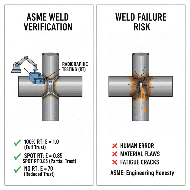
3. Welded Joints: Why ASME Never Fully Trusts Them
In real accident investigations, welds almost always appear as risk concentration points.
ASME acknowledges this reality explicitly through the Joint Efficiency (E) factor in design calculations:
No radiographic testing: E = 0.70
Spot or partial RT: E = 0.85
Full RT (100%): E = 1.00
Radiographic testing (RT) is a nondestructive method used to detect internal weld defects.
ASME’s logic is straightforward:
Welds may contain defects.
The more thoroughly they are inspected, the more confidence the design calculation is allowed to place in them.
This is not a punishment — it is engineering honesty.
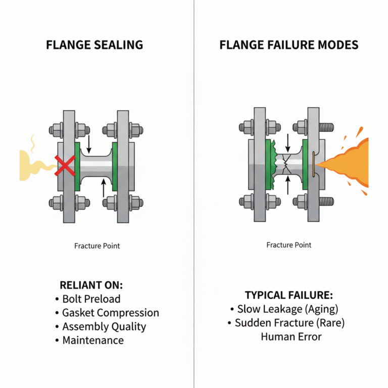
4. Why Flanges Are High-Risk Components in ASME Systems
If welds are unavoidable weak points, flanges are the most human-dependent ones.
Unlike welded joints, flanges:
Are not continuous structures
Rely on bolt preload and gasket compression
Are highly sensitive to assembly and maintenance quality
Operational experience consistently shows that flange failures are rarely caused by insufficient strength.
They are far more often caused by loss of sealing performance.
ASME Standards Governing Flanges
What engineers casually call “ASME flanges” are actually governed by multiple standards:
ASME B16.5 — NPS ½ to 24 (most common)
ASME B16.47 — NPS 26 to 60
ASME B31 / BPVC — system-level usage conditions
In simple terms:
B16 defines what a flange can handle
B31 / BPVC define whether you are allowed to use it that way
Flange Class: Not a Pressure Value
Flange Class (150, 300, 600, etc.) is often misunderstood.
Class is not a pressure rating.
It represents a pressure–temperature capacity for a specific material.
For example, carbon steel A105 at ambient temperature:
Class 150 ≈ 19 bar
Class 300 ≈ 51 bar
As temperature increases, allowable pressure drops significantly — always subject to tabulated limits.
ASME pressure–temperature rating tables exist to prevent experience-based guessing under changing conditions.
Flange Face Types and Sealing Risk
Common ASME flange facing types include:
RF (Raised Face) — most common, gasket-based sealing
FF (Flat Face) — low-pressure systems only; not interchangeable with RF
RTJ (Ring Type Joint) — high-pressure/high-temperature, metal-to-metal sealing
ASME does not mandate one selection —
it constrains choices through operating limits and historical failure data.
Typical Flange Accidents
In chemical and energy facilities, the most frequent flange incidents are progressive leaks, not ruptures.
Common characteristics:
No obvious abnormalities at startup
Leakage develops over time
Often linked to bolt relaxation, gasket aging, or thermal cycling
ASME treats flanges as sealing structures, not continuous pressure boundaries.
It does not promise “zero leakage”.
It aims to prevent:
Sudden flange fracture
Instantaneous large-scale release of hazardous media
Systemic failure caused by improper selection
5. Why ASME Insists on Pressure Testing
Pressure testing — typically hydrostatic testing — is a critical post-fabrication verification step.
In ASME UG-99, the standard test pressure is approximately:
1.3 × design pressure, adjusted for material allowable stress at test temperature
The objective is not to simulate operation.
It is to:
Expose fabrication and welding defects under controlled conditions
Prevent defects from revealing themselves during service — in a far more dangerous manner
Accident reviews frequently conclude:
“This issue could have been detected during proper pressure testing.”

6. How ASME Protection Is Often Weakened in Practice
When ASME “fails” in real projects, it is rarely because the code is unreasonable.
More commonly, it is because:
Flange class is downgraded to reduce cost
Material substitutions are made without recalculation
Welding and inspection scope is reduced
Documentation and traceability are incomplete
Individually, these may seem minor.
Together, they systematically erode the safety margin ASME was designed to provide.
ASME Is a Safety Baseline, Not a Guarantee
ASME does not guarantee perfect equipment.
It explicitly accepts that:
Local plastic deformation may occur
Minor leakage may be unavoidable
Human error cannot be fully eliminated
What ASME seeks to prevent is:
Sudden, catastrophic structural failure
Uncontrolled high-energy release
Engineering accidents without accountability

Conclusion
ASME increases cost, workload, and coordination effort.
But accident history consistently shows that it limits the worst possible outcomes of engineering failure.
For engineers, ASME is best understood as a baseline rule set:
You may optimize above it.
Once you cross below it, the price of failure is almost always higher than the cost you saved.