Orifice plate flowmeters are widely used in industrial flow measurement due to their simple structure and standardized design. However, because the measurement principle is based on differential pressure, their performance is highly sensitive to installation conditions, process parameters, and impulse piping systems.
In practical applications, most failures can be classified into two main categories:
Abnormal measurement values (high, low, or unstable readings)
No display or no output signal
Effective troubleshooting requires a systematic investigation covering the orifice plate itself, impulse lines, transmitter configuration, and actual process conditions.
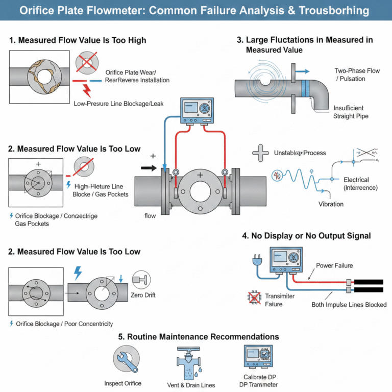
1. Measured Flow Value Is Too High
1.1 Orifice Plate Problems
The inlet edge of the orifice plate is worn, deformed, corroded, or fouled, increasing the effective flow area.
Incorrect installation direction. The “+” mark should face the upstream flow; reverse installation can cause abnormal differential pressure.
Corrective actions:
Remove and inspect the orifice plate. Replace it if wear or deformation is significant.
Reinstall the orifice plate in the correct flow direction.
Ensure gaskets do not protrude into the pipe bore.
1.2 Impulse Line Problems
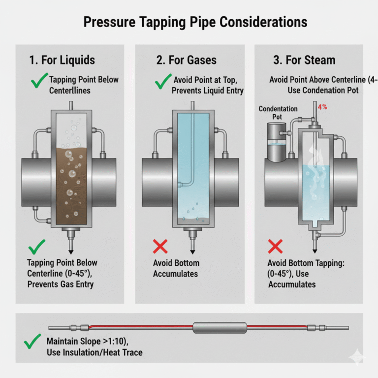
Blockage, leakage, or insulation/heating failure on the low-pressure side, leading to condensation and reduced sensed pressure.
A reduced low-pressure signal results in an artificially high differential pressure reading.
Corrective actions:
Clear blockages in the low-pressure impulse line.
Inspect welds and fittings for leaks and repair as needed.
Restore insulation or heat tracing and drain accumulated condensate.
1.3 Configuration and Parameter Errors
Incorrect density, pressure, or temperature values configured in the DCS or secondary instrument.
Measurement range set too narrow.
Corrective actions:
Re-measure actual process conditions and correct all configuration parameters.
Verify and adjust the measurement range according to real operating conditions.
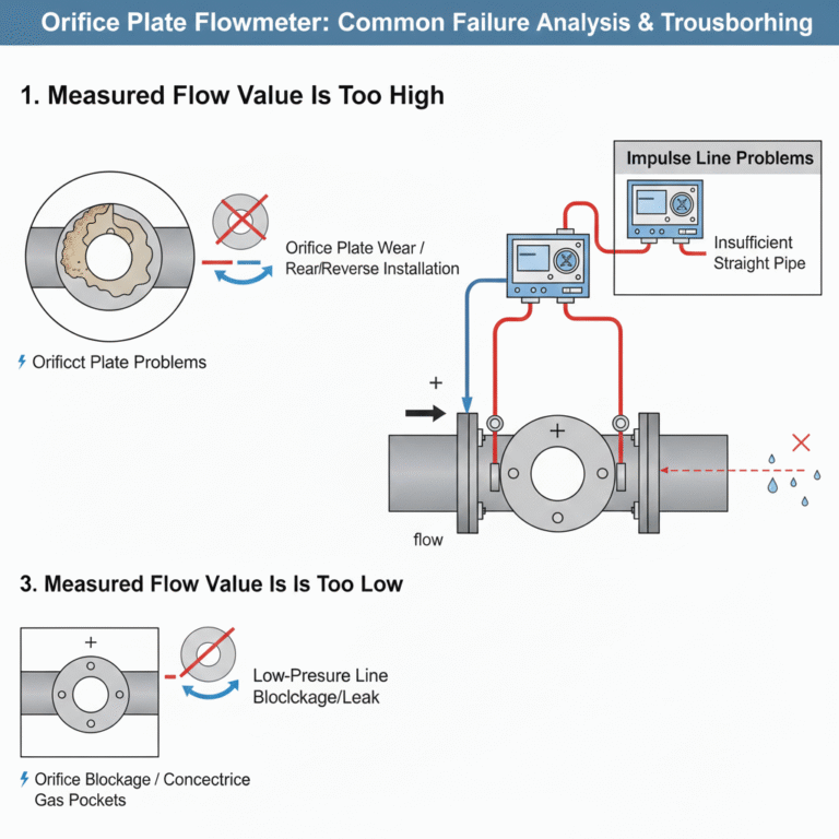
2. Measured Flow Value Is Too Low
2.1 Orifice Plate Problems
Foreign material partially blocking the orifice opening, reducing effective flow area.
Poor concentricity between the orifice plate and the pipeline, causing flow disturbances.
Corrective actions:
Clean any blockage at the orifice opening.
Re-align the orifice plate to meet concentricity requirements specified by standards.
2.2 Impulse Line Problems
Blockage or leakage on the high-pressure side.
Gas pockets trapped in impulse lines, resulting in inaccurate pressure transmission.
Corrective actions:
Clear blockages and repair leaks on the high-pressure side.
Vent impulse lines to remove trapped gas.
For gas-containing liquids, consider installing a gas–liquid separator.
2.3 Transmitter Issues
Zero drift of the differential pressure transmitter.
Transmitter range selected too large for actual operating flow.
Corrective actions:
Perform zero calibration on the differential pressure transmitter.
Verify the range and recalibrate the transmitter if necessary.
2.4 Process Condition Limitations
Actual flow rate is below the lower measurement limit.
Orifice plate flowmeters exhibit significantly reduced accuracy at low flow rates.
Corrective actions:
Replace the orifice plate with one designed for a lower flow range.
Apply low-flow compensation methods where applicable.
3. Large Fluctuations in Measured Value
3.1 Unstable Process Conditions
Two-phase flow (gas–liquid mixture).
Pulsating flow or frequent pressure and temperature variations.
Corrective actions:
Install pulsation dampeners or flow stabilizers upstream.
Optimize process conditions to stabilize pressure and temperature.
For two-phase flow, install suitable separation devices.
3.2 Installation Conditions Not Met
Insufficient straight pipe lengths upstream or downstream.
Typical standard orifice plates require ≥10D upstream and ≥5D downstream (D = pipe internal diameter).
Flow disturbances caused by upstream elbows, valves, or fittings.
Corrective actions:
Modify piping to increase straight pipe lengths.
Install flow conditioners if sufficient straight runs cannot be achieved.
3.3 Instrumentation and Piping Issues
Impulse lines not securely fixed and affected by vibration.
Damping settings in the transmitter or DCS are too low.
Corrective actions:
Secure impulse lines with proper supports.
Increase damping time appropriately to suppress high-frequency noise.
3.4 Electrical Interference
Signal cables routed together with power cables, introducing electromagnetic interference.
Corrective actions:
Route signal and power cables separately.
Use shielded cables and ensure proper grounding.

4. No Display or No Output Signal
4.1 Power Supply Issues
Power supply failure, loose wiring, or open circuits.
Safety barrier malfunction interrupting power.
Corrective actions:
Verify supply voltage and tighten all terminals.
Replace faulty safety barriers if required.
4.2 Transmitter Failure
Sensor damage inside the differential pressure transmitter.
Failure of internal electronics.
Corrective actions:
Perform transmitter self-diagnostics.
Replace the sensor or the entire transmitter if repair is not feasible.
4.3 Impulse Line Blockage
Both high-pressure and low-pressure impulse lines are blocked, resulting in zero differential pressure.
Corrective actions:
Thoroughly clean impulse lines.
Remove and flush piping if necessary.
5. Routine Maintenance Recommendations
Periodically inspect the orifice plate for wear, corrosion, or fouling. Shorten inspection intervals for corrosive or particle-laden media.
Regularly vent and drain impulse lines. Verify the effectiveness of insulation and heat tracing to prevent condensation or freezing.
Perform routine zero and span calibration of differential pressure transmitters.
Avoid any piping modifications within the upstream and downstream straight pipe sections, as this can disrupt the flow profile.

Engineering Summary
In most cases, apparent “instrument failures” of orifice plate flowmeters are not caused by the transmitter itself, but by installation conditions, impulse line problems, or changes in process parameters. A systematic troubleshooting approach focusing on the entire measurement system is essential for restoring accurate and stable flow measurement.