In industries such as chemical, water treatment, and metallurgy, electromagnetic flowmeters have become the go-to solution for measuring conductive fluid flow, thanks to their no pressure loss, corrosion resistance, and excellent linearity. However, issues like weak signals prone to interference, improper grounding causing data drift, and installation errors affecting accuracy often challenge instrument technicians.
PART 01: What is an Electromagnetic Flowmeter? Pros & Cons
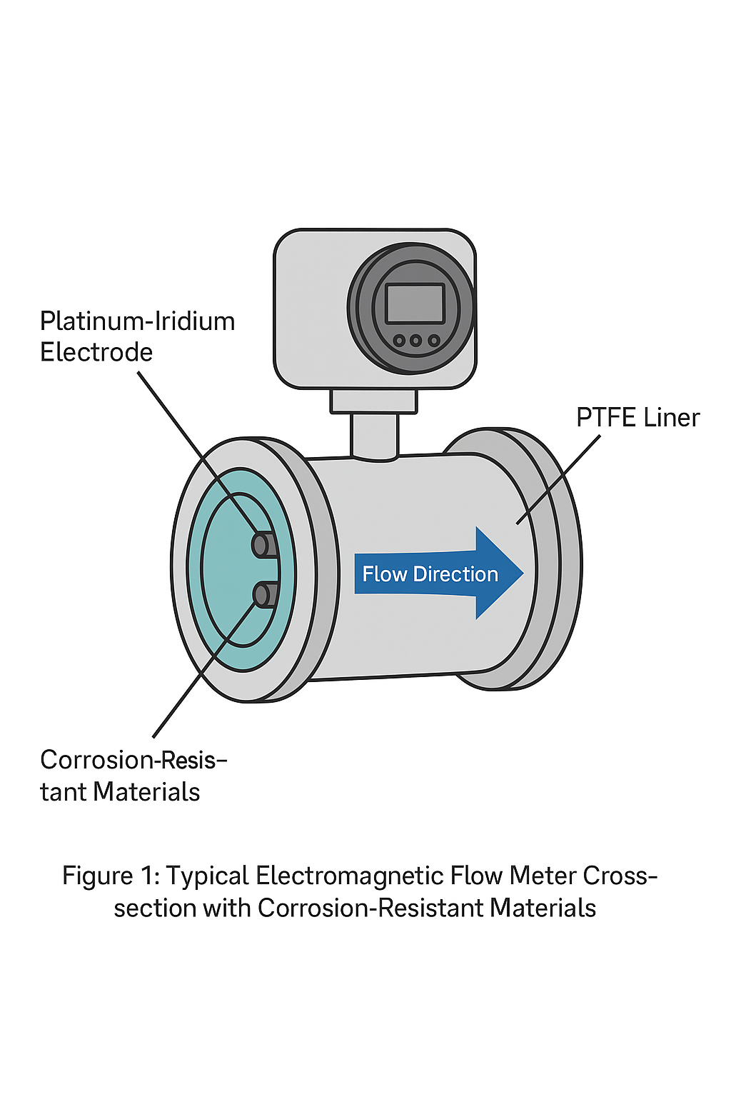
Electromagnetic flowmeters operate on the principle of electromagnetic induction: when a conductive medium flows through a magnetic field, it cuts magnetic lines of force, inducing a weak electromotive force proportional to the flow rate. The device consists of a sensor (including measuring tube, electrodes, and excitation coils) and a converter (for signal processing and output), connected via a dedicated cable.
Key Advantages:
No moving parts or flow obstruction; smooth measuring tube ensures minimal pressure loss, ideal for large-diameter applications.
Strict linear relationship between output and flow rate; wide measuring range (2.5 mm to 3 m pipe diameter) with a turndown ratio up to 1:20.
Adaptable to corrosive media (e.g., strong acids, alkalis) via selectable linings (PTFE, rubber) and electrode materials (316L, Hastelloy).
Flexible installation with upstream straight pipe requirement of only 5D and downstream 3D—far less than orifice plates or turbine meters.
High accuracy (±0.2% to ±0.5%), suitable for industrial precision measurement.
Limitations:
Medium must be conductive (minimum conductivity >5 μS/cm); cannot measure gases, steam, petroleum products, etc.
Temperature and pressure limits: typically ≤180°C and ≤4.0 MPa for standard models.
Medium should not contain excessive ferromagnetic materials or air bubbles, which can distort the magnetic field and affect measurement.
PART 02: Why Grounding is the “Lifeline” of Electromagnetic Flowmeters
The measurement signal of an electromagnetic flowmeter is extremely weak—only 2.5–8 mV at full scale, dropping to microvolts at low flow rates. Any external electromagnetic interference can overwhelm the true signal, causing data drift and reduced accuracy. Proper grounding is essential to shield against interference and ensure signal stability.
Four Key Grounding Requirements:
Ground All Components
The sensor’s measuring tube, housing, signal shield, converter, and secondary instruments must each be grounded to form a complete shielding loop.Use a Dedicated Grounding Point
Never connect to motor grounds, process piping, common electrical grounds, or water pipes. Use a separate grounding electrode with resistance <10 Ω.Single-Point Grounding
Ground the sensor and converter at the field site; ground the signal shield only on the control room side to avoid ground-loop interference.Special Installation Grounding
For metal pipes (without insulation coating), ground directly via the sensor’s grounding terminal. For plastic or insulated-lined pipes, install grounding rings (or short pipes with grounding electrodes) at both ends to establish a zero-potential loop between the medium and earth.
PART 03: Comparison of Three Excitation Methods—How to Choose?
The magnetic field is the foundation of electromagnetic flow measurement and must be stable and uniform. Here are the three mainstream excitation methods:
1. DC Excitation (Permanent Magnet / DC Power)
Pros: Strong resistance to AC electromagnetic interference; negligible liquid self-induction effects.
Cons: Risk of electrode polarization (ions accumulating around electrodes), increasing internal resistance; bulky and costly for large pipes.
Best for: Small pipes, low flow rates, non-polarizing media.
2. AC Excitation (50 Hz Mains Frequency)
Pros: Eliminates electrode polarization; lower sensor impedance; AC signals are easier to amplify.
Cons: AC magnetic flux can cause quadrature interference (same frequency, 90° out of phase), potentially overwhelming the true signal.
Best for: General applications with moderate accuracy requirements and no strong polarization.
3. Constant Current Square-Wave Excitation
Pros: Combines benefits of both DC and AC—avoids polarization and quadrature interference; supports sensor calibration and interchangeability; stable without complex compensation circuits.
Cons: Slightly higher technical cost.
Best for: Most industrial applications, especially high-precision measurement, corrosive media, and large-diameter pipelines (current industry standard).
PART 04: Six Installation Details That Determine Measurement Accuracy
Theoretical advantages only translate into performance with proper installation. Pay close attention to these six points:
Orientation: Ensure Full Pipe
Install vertically, horizontally, or at an angle, but always keep the tube full.
Prefer vertical installation (upward flow) to vent air. In horizontal installation, keep electrodes level to avoid sedimentation or bubble interference.
For slurry or solid-laden fluids, always install vertically to prevent uneven liner wear.Straight Pipe Length: Ensure Uniform Flow
Upstream: ≥5D (extend to ≥10D if valves, expanders, or other disturbances are present).
Downstream: ≥3D. Keep conical expander angles <15° to avoid flow disturbance.
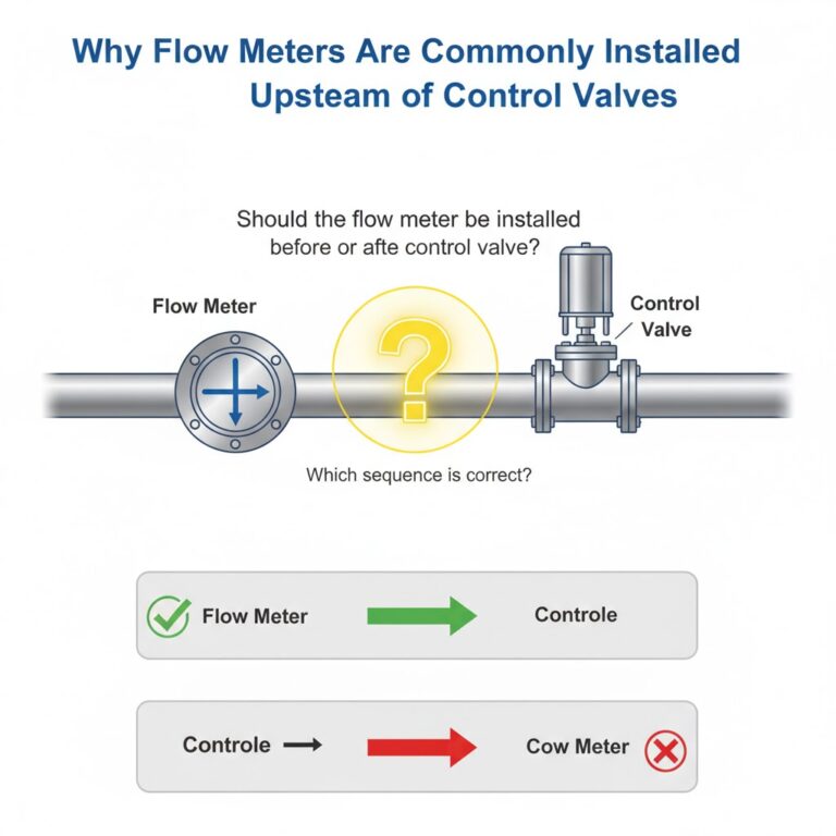
Place control valves downstream; upstream shut-off valves must be fully open. If not, align valve disc 45° to electrode axis.Keep Away from Interference Sources
Avoid high-power motors, transformers, VFDs, etc.
Run signal and excitation cables in separate steel conduits; avoid running parallel to power cables.Cable Selection and Routing
Use manufacturer-specified shielded cables only.
Keep signal cables short; mount the converter close to the sensor. Minimize exposed cable ends; strip shield only enough for terminal connection.Power Supply Matching
Sensor and converter must use the same phase power to avoid 120° phase mismatch between detection and feedback signals.Grounding (Reinforcing Part 02)
Ground sensor housing, measuring tube, and piping separately, following single-point grounding strictly.
PART 05: Commissioning Procedure
Seven Steps to Stable Measurement:
Slowly open valves to fill the system, ensuring no air pockets.
Check flange and pipe connections for leaks.
If one side leaks, loosen opposite flange bolts slightly while tightening the leaking side.
If leak persists, inspect the liner (lightly sand if damaged).
Vent the system completely to remove trapped air (bubbles disrupt magnetic field and electrode contact).
Power up the sensor and converter and allow warm-up (typically 30 minutes, refer to manual).
Close the valve to keep medium static in the sensor, then adjust converter zero point.
Reopen the valve gradually to 100% flow; verify output accuracy and stability.
Run continuously for 24 hours, log data, and confirm no drift before official operation.
PART 06: Summary & Tips
Key Selection Considerations:
Media conductivity, temperature, pressure, solid/bubble content, pipe size, and straight-run availability.
Troubleshooting Data Drift:
First check: grounding, electromagnetic interference, and whether pipe is full.
Corrosive Media Measurement:
Match liner and electrode material (e.g., PTFE liner + Hastelloy electrode for strong acids).
Complex Conditions (High Temp/Pressure, High Viscosity, Strong Corrosion):
Consult manufacturers for customized solutions to avoid mismatch and measurement failure.