In process automation, control valves are the final elements responsible for executing the control signal. However, due to friction, fluid forces, actuator limitations, and other mechanical factors, the actual valve position often fails to match the input signal.
A valve positioner—commonly referred to simply as a “positioner”—is the key device designed to eliminate this deviation.
A positioner does not throttle the medium. Instead, it amplifies a low-power control signal into a pneumatic output capable of driving the actuator, and forms a local closed-loop with valve-stem feedback to ensure the valve stabilizes precisely at the required position.
Below is a systematic overview of what a positioner is, how it works, when it is needed, and why it determines the performance quality of a control valve.

1. A Positioner Is a Local Servo Controller for Control Valves
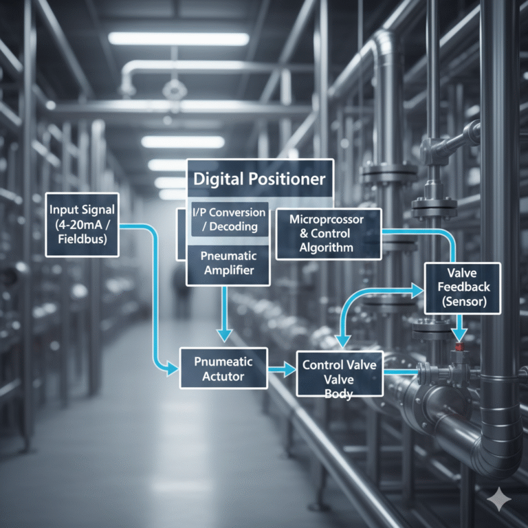
Functionally, a positioner is part of the control valve assembly. It builds a local servo loop consisting of “input signal → actuator air pressure → valve position feedback.” Its purpose is to improve valve accuracy, responsiveness, and disturbance rejection.
The signal chain typically includes four components:
Input: Accepts a 4–20 mA, pneumatic, or fieldbus signal; performs I/P conversion or digital decoding.
Comparison & Control: Compares the setpoint with feedback and adjusts output pressure based on the error. Traditional units use mechanical force-balance; modern units use digital computation.
Pneumatic Amplification: Uses supply air to generate sufficient power to overcome spring force, friction, and fluid forces.
Feedback: Mechanical linkages or sensors capture valve position and complete the closed loop.
In control theory, this is a classic servo system. The DCS only needs to send a setpoint. The positioner ensures the valve responds predictably and accurately—making it essential for high-performance control.
2. How Positioners Work
Two major design principles are widely used:
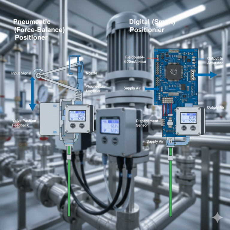
(1) Pneumatic (Force-Balance) Positioners
They operate using a nozzle–flapper mechanism:
Signal deviation causes back-pressure changes.
Pneumatic amplifiers convert back-pressure to actuator output.
Mechanical feedback closes the loop.
Advantages:
Very robust, easy to maintain, resistant to harsh environments. Suitable for many general-purpose applications.
(2) Digital (Smart) Positioners
Digital positioners use a microprocessor and displacement sensor to:
Measure valve position
Compute control output
Drive piezo valves or high-speed nozzles
Advantages:
Better linearization, adjustable gain, auto-tuning, and built-in diagnostics. The real value lies in repeatability and valve condition monitoring—not just “being smart.”
3. Why Valves Cannot Accurately Follow the Signal Without a Positioner
Without a positioner, the actuator relies solely on springs and mechanical balance. This cannot overcome several fundamental issues:
Friction & Hysteresis: Packing friction causes deadband and reverse hysteresis.
Fluid Forces: Pressure/flow changes create side loads that shift valve position.
Insufficient Driving Force: Variations in air supply or oversized actuators limit responsiveness.
Nonlinear Mechanics: Required force varies dramatically across the stroke.
These factors mean the valve cannot reliably “track” the input signal. A positioner compensates by creating a tight feedback loop.
4. When a Positioner Is Essential
A positioner is not required for every valve, but it becomes critical in the following situations:
High control accuracy is required
(pressure, temperature, level, ratio control, etc.)Valves with high friction or stiff mechanical structures
(metal-seated valves, high-pressure valves, bellows valves)Strong fluid-dynamic forces
(steam service, high ΔP flow, slurry, or high-velocity media)Large actuators or fast response requirements
Applications requiring a defined fail-safe strategy
In short:
If “accurate and stable valve positioning” matters, a positioner is the most reliable solution.

5. Clarifying Commonly Confused Concepts
To avoid miscommunication:
Control Valve = Valve body + actuator + accessories (including positioner)
I/P Converter = Converts 4–20 mA to pneumatic signal; no feedback loop; not a positioner
Solenoid Valve = For on/off control; cannot perform continuous positioning
Also note:
“Positioner” may refer to different devices in different industries—clarification is important during design and procurement.
6. How to Evaluate a Positioner’s Performance
Key performance indicators include:
Basic error & linearity
Hysteresis
Sensitivity & deadband
Air capacity & dynamic response
Environmental ratings (IP, explosion-proof, corrosion resistance)
Matching these parameters to the application determines control quality—not just selecting “smart” vs. “non-smart.”

7. Engineering Best Practices for Installation & Commissioning
The quality of installation often matters more than the device itself:
Ensure feedback direction and stroke mapping are correct—wrong direction causes oscillation.
Zero/span calibration must reference mechanical limits.
Maintain clean and stable supply air—contamination leads to clogging or sticking.
Protect against vibration and high temperature to prevent sensor drift and fatigue.
Define bypass and switching strategies ahead of commissioning.
These factors heavily influence long-term stability.
8. The Positioner’s Role Is Evolving: From “Driving” to “Diagnostics”
Digital positioners now provide vital insights into valve health:
Friction trends
Hysteresis and deadband development
Response time and dynamic quality
Early detection of mechanical degradation
This transforms the valve from a “black-box device” into a measurable asset, enabling predictive maintenance.
The goal is not cloud computing, but accurate, accessible data that guides maintenance and replacement planning.

9. Conclusion
The value of a positioner is not about how “smart” or “advanced” it looks, but its ability to ensure the valve follows the control signal accurately, stably, and predictably.
Whether using a pneumatic or digital design, the core mission is the same:
To make the control valve respond exactly as required — and to verify, maintain, and predict its performance over time.