In piping systems, the type of flange seal face often determines the upper limit of the entire sealing system. While many focus on flange material and pressure ratings, the importance of matching seal faces is often overlooked. The seal face plays a crucial role in:
Gasket compression ability
Corrosion resistance to the medium
Ease of disassembly and maintenance
Leak probability (especially in volatile VOC pipelines)
A flange seal face is essentially the “seat” of the sealing system. If the seat design is poor, even the best gasket won’t sit properly.
Starting from the relationship between contact area and material stiffness, we delve into the deeper logic of seal faces such as FF, RF, RTJ, TG, LMF, and SJ.
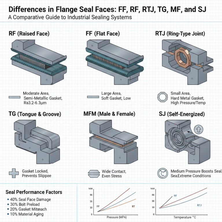
1. Seal Face Area, Gaskets, and Pressure
In general:
The larger the seal face area, the lower the unit pressure, requiring softer gaskets that compress more easily.
The smaller the seal face area, the higher the unit pressure, requiring harder gaskets to withstand high pressure and form a metal seal.
This is because soft materials compress easily under low pressure, whereas hard materials (especially metal gaskets) require higher pressure to undergo plastic deformation. Thus, the most common flange structures exhibit the following patterns:
FF has the largest sealing area, requiring soft gaskets like rubber or fiber.
RF has a moderate sealing area, using semi-metal gaskets like graphite wound gaskets.
RTJ has the smallest sealing area, requiring metal ring gaskets.
These designs are not arbitrary but are the result of a comprehensive consideration of thermodynamics, mechanics, and material properties.
2. Common Seal Face Types
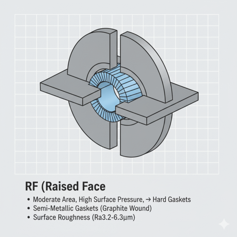
1. RF (Raised Face Seal)
RF flanges are characterized by a raised circular seal face that protrudes from the flange’s bolt connection plane, forming an independent compression zone. This increases the unit area pressure under limited torque. The principle is to enable the metal ring gasket to plastically deform under high preload, embedding into the flange groove to achieve a metal-to-metal seal. RF flanges are commonly used in the petroleum, natural gas, and chemical industries. However, their sealing stability decreases in environments with large temperature fluctuations or volatile media.
Small sealing area, high surface pressure, hard gaskets
Surface roughness (Ra3.2-6.3μm) is essential to create micro-grooves, enhancing gasket embedding. If too smooth, leakage can increase.
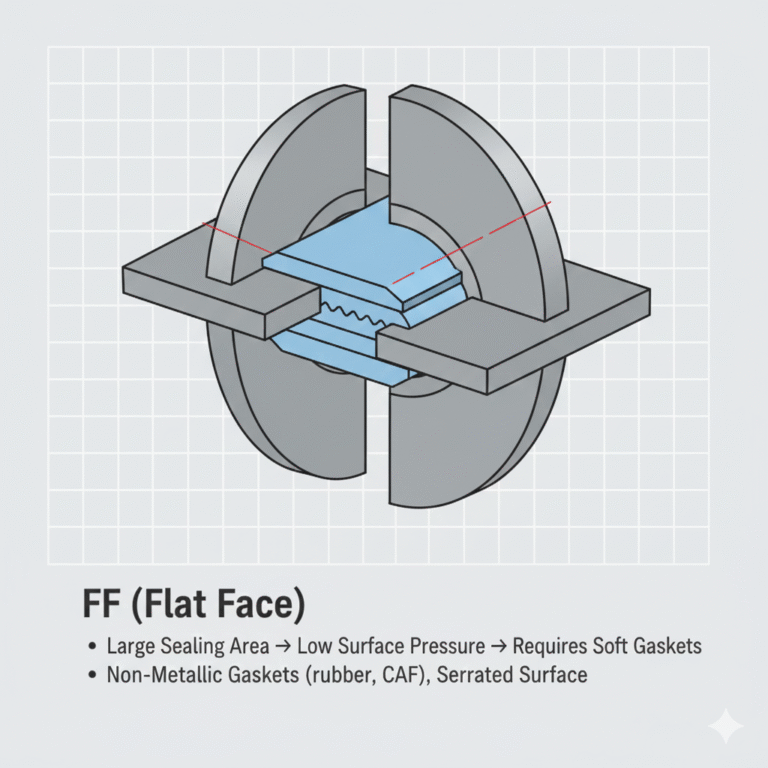
2. FF (Flat Face Seal)
The FF design does not improve sealing performance but protects brittle materials like cast iron. The sealing face is in the same plane as the flange’s bolt face, with the gasket extending from the inner diameter to the outer diameter, forming a “full flat” sealing structure. The sealing mechanism relies on “low surface pressure + uniform compression,” requiring soft, high-deformation, high-rebound gaskets.
Large sealing area → low surface pressure → requires soft gaskets
Non-metallic gaskets (rubber, CAF) are commonly used, and the sealing surface must have serrations.
FF flanges are suitable for low-pressure applications, typically at pressure ratings of 125 and 250.
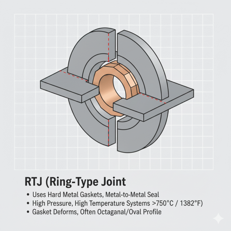
3. RTJ (Ring-Type Joint Seal)
RTJ flanges are a variant of the raised face design, often used in more demanding applications, especially high-pressure and/or high-temperature systems (>750℃ / 1382℉). RTJ flanges can be used across all pressure ratings but are commonly found in 900 and higher pressure systems.
Uses metal (hard) gaskets instead of soft or semi-metal gaskets, providing a metal-to-metal seal.
RTJ gaskets are made from softer materials than the flange material to ensure that the gasket deforms to form the seal.
Oval or octagonal groove profiles distribute sealing stress more effectively, with BX gaskets self-tightening under internal pressure for improved sealing at high pressures.
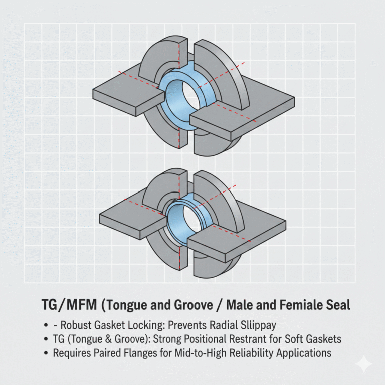
4. TG/MFM (Tongue and Groove / Male and Female Seal)
TG and MFM flanges provide robust locking of the gasket, preventing radial slippage due to uneven bolt compression, vibration, or temperature changes.
TG (Tongue & Groove): One side is convex (Tongue), and the other is concave (Groove), providing strong positional restraint, especially for soft gaskets.
MFM (Male & Female): One side is convex (Male), and the other is concave (Female), offering a wider contact area, ensuring a more even stress distribution.
Both are used in mid-to-high reliability scenarios and require paired flanges.
5. LMF/LCF (Large Male and Female Seal)
This seal design is used primarily for pressure vessel equipment, with an enlarged contact area that allows the gasket to operate over a broader surface pressure range, reducing the impact of machining tolerances and improving connection reliability.
6. SJ (Self-Energized Seal)
Self-energized seals, such as C-type, O-ring metal gaskets, and lens gaskets, rely on the medium’s pressure to provide additional sealing pressure. These are typically used in extreme conditions such as cryogenic, high-temperature, and pulsating pressure systems.
High-pressure, high-temperature sealing is ideal for specialized equipment in aerospace and chemical industries.
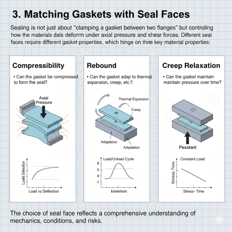
3. Matching Gaskets with Seal Faces
Sealing is not just about “clamping a gasket between two flanges” but controlling how the materials deform under axial pressure and shear forces. Different seal faces require different gasket properties, which hinge on three key material properties:
Compressibility: Can the gasket be compressed to form a seal?
Rebound: Can the gasket adapt to thermal expansion, creep, etc.?
Creep Relaxation: Can the gasket maintain pressure over time?
4. Industry Preferences for Different Seal Faces
Different industries prioritize different risk factors:
Petrochemical Industry: High temperature + high pressure → prefers RTJ, MFM for critical equipment sealing.
Natural Gas Transmission: Leakage consequences (flammable + regulatory) → TG/MFM, RTJ for improved sealing.
Fine Chemicals: Corrosion + VOC emissions → PTFE gaskets + TG/MFM.
Water Treatment: Cost + material lifespan → RF/FF is sufficient.
Cryogenics & Aerospace: Extreme temperature gradients + gas leakage → self-energized seals are ideal.
5. Causes of Seal Failure
Studies show that seal failure is mainly caused by:
40% from seal face damage or roughness non-compliance
30% from insufficient or uneven bolt preload
20% from improper gasket matching
10% from material aging or extreme conditions
Seal face selection accounts for 70% of the impact on seal performance. Even with the best gasket, an improper seal face design will result in failure.
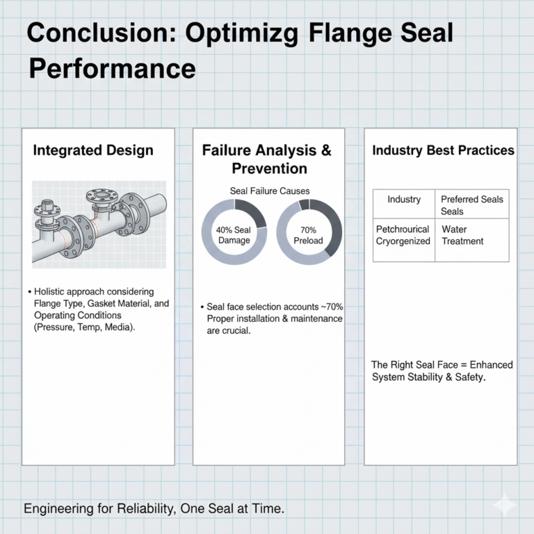
Conclusion
Sealing is not based on experience alone or using just any gasket. The choice of seal face reflects a comprehensive understanding of mechanics, materials, conditions, and risks. When the correct seal face is chosen, the system’s stability can be enhanced by a significant margin.