A float is connected to a rope, which is suspended on a pulley, and the other end of the rope is attached to a counterweight. The float floats on the liquid surface, and the difference between the gravitational force and buoyant force acting on the float is balanced by the counterweight, thus achieving equilibrium:
Where:
is the weight of the float (N)
is the weight of the counterweight (N)
is the buoyant force on the float (N)
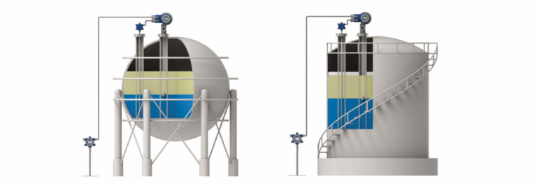
In practical applications, the constant buoyancy level measurement device can use various structural forms to convert the liquid level into displacement. A mechanical transmission mechanism can drive a pointer to display the liquid level on-site. If a displacement-to-electricity conversion circuit is added, the displacement can be converted into an electrical signal, allowing for remote transmission of the liquid level measurement signal.
The constant buoyancy measurement relies on a rope-and-weight system. Besides the counterweight’s gravitational force, the rope’s length (L1 and L2) and its own weight, as well as the friction of the pulley, affect the equilibrium. These external forces alter the balance, causing the float’s immersion depth to vary, resulting in measurement errors.
The gravitational load applied by the rope varies with the liquid level, adding a fluctuating component to the constant counterweight’s gravitational force, which inevitably causes errors. However, this error is predictable and can be corrected during calibration.
The frictional force causes the largest error and is direction-dependent, making it irreparable. The best solution is to increase the buoyancy force to reduce its impact. The float’s positioning force, which refers to the increase in buoyant force caused by the movement of the immersion line (
), can be significantly increased by using a larger diameter float. This is the most effective method to minimize friction-related errors, especially when the measured medium has low density.
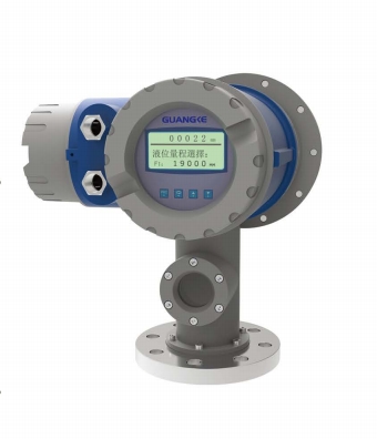
Float-type and ball-type level gauges are typical constant buoyancy level meters.
Servo-type Level Meter:
The servo-type level meter operates on the principle of buoyancy balance and uses a micro-servo motor to drive a small float, accurately measuring liquid levels and other parameters. During operation, the gravitational force on the float acts on a fine steel wire, generating torque on the external magnetic drum. This causes a change in the magnetic flux.
The change in magnetic flux between the drum components alters the output voltage signal from the electromagnetic sensor (Hall element) on the internal magnet. The voltage value is compared with a reference voltage stored in the CPU. When the float is in a balanced position, the difference is zero. When the liquid level changes, the float’s buoyant force is altered.
This results in a change in the magnetic coupling torque, which in turn changes the output voltage of the Hall element with temperature compensation. The voltage difference, compared to the reference voltage in the CPU, drives the servo motor to adjust the float’s position, restoring balance.
This entire system forms a closed-loop feedback mechanism (as shown in the diagram), with an accuracy of ±0.7mm. The system includes a load compensation feature that compensates for changes in wire tension caused by the attachment of the measured medium to the steel wire or float.
The servo-type level meter mainly consists of components such as the float, steel wire, magnetic coupling mechanism, transmission shaft, tension detection mechanism, transmission mechanism, motor, display, and core processor. The float is suspended inside a housing, with a highly flexible and strong stainless steel wire wound uniformly on a drum. The grooves at the bottom of the drum are flat, with each groove containing a single wire. The float’s density is greater than that of the measured liquid, and with the proper tension, half of the float is submerged in the liquid, maintaining a balanced measurement state.
The measurement principle relies on Archimedes’ principle, one of nature’s fundamental laws. Essentially, the level is determined by measuring the tension in the wire, allowing the liquid level to be identified.
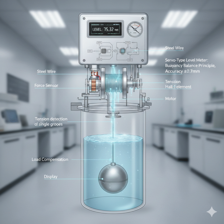
The servo level meter includes the terminal part, electronic components, magnetic drum chamber, measuring steel wire, float, etc. The wire carrying the float is wound in the grooves of the magnetic drum surface, and the motor unit is mounted on the shaft of the drum. The motor transfers torque to the force sensor, which converts the torque into a frequency signal. The servo processing unit receives the frequency from the force sensor and controls the motor to adjust the float’s position.