In the field of instrumentation, theoretical knowledge is like the wrench in your hand — it might seem insignificant, but if you lack it, it can cause problems when you need it most! Whether you’re preparing for certification exams or aiming to strengthen your practical skills, understanding circuit diagrams, sensor principles, and troubleshooting logic is essential. This series will keep updating, helping you tackle theoretical concepts while also building a solid foundation for hands-on operations. Even in short bursts of free time, you can gradually develop a strong skill set. For those looking to avoid detours and quickly fill knowledge gaps, let’s solidify the theoretical foundation to gain more confidence in real-world tasks!

How Does a Turbine Flowmeter Work? What Are Its Advantages and Disadvantages?
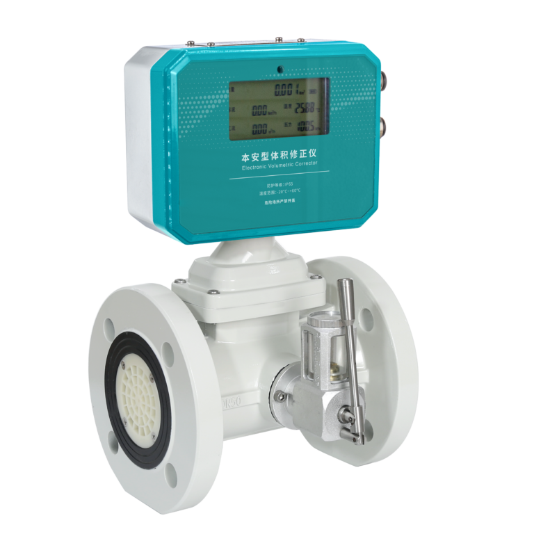
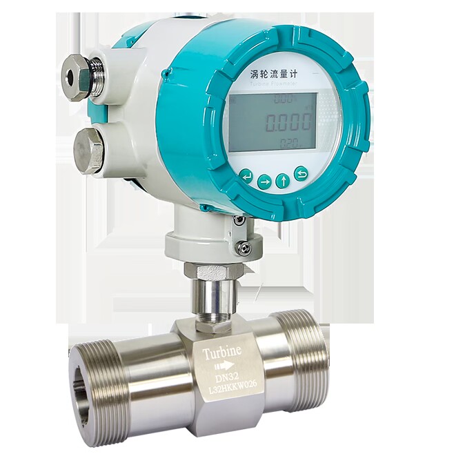
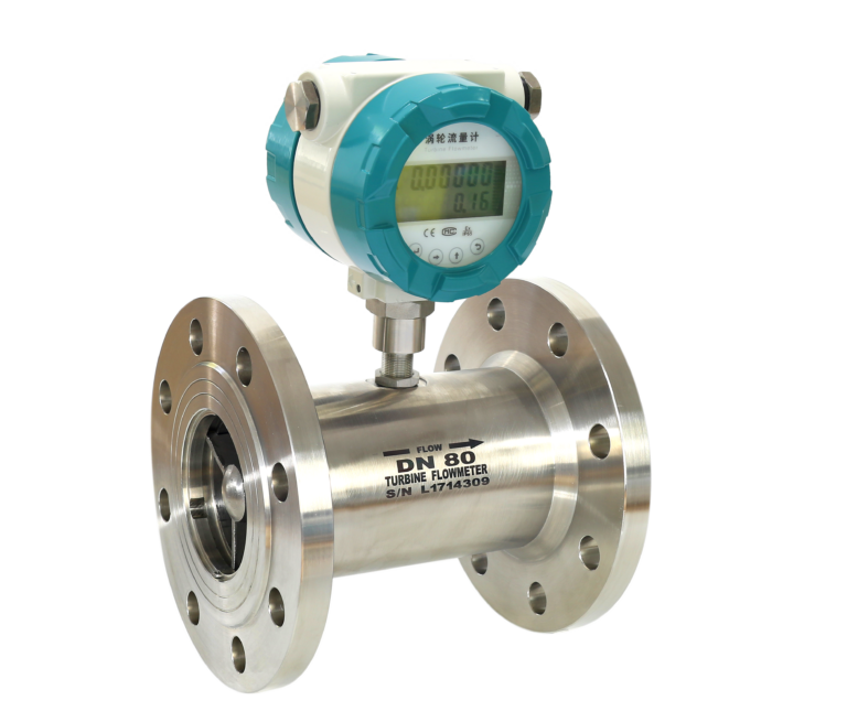
A turbine flowmeter works based on the momentum principle of the fluid. When the measured fluid passes through the flowmeter sensor, it impacts the turbine blades, causing the turbine to rotate. Within a certain flow range and under specific fluid conditions, the turbine’s rotational speed is proportional to the flow rate. By measuring the turbine’s speed, the flow rate of the fluid can be determined.
Advantages of Turbine Flowmeters:
High Accuracy: Typically, accuracy levels are ±0.5% and ±0.2%.
Wide Range: The ratio of maximum to minimum linear flow rate is between 6:1 and 10:1.
Quick Response: Due to low inertia, it can quickly detect fluctuating flow.
High Pressure Resistance: The pressure loss is low.
Compact Design: The small size of the instrument allows for easy installation and maintenance.
Disadvantages of Turbine Flowmeters:
Calibration Condition Dependency: The instrument constant is usually calibrated at standard conditions (water at room temperature), and any deviation from these conditions (e.g., changes in fluid properties) can cause measurement errors.
Wear and Tear: The turbine rotates at high speeds, causing wear on moving parts. If components like the shaft or bearings are replaced, recalibration of the instrument constant is required. Typically, users do not have the means to perform such recalibrations.
Sensitivity to Impurities: Turbine flowmeters cannot measure fluids with significant impurities. Adding filters before the flowmeter increases fluid resistance and requires regular maintenance of the filter.
Temperature, Density, and Viscosity Variations: Since turbine flowmeters measure volumetric flow, changes in fluid temperature, density, and viscosity can affect the readings. Compensation mechanisms are required for accurate data.
Installation Requirements for Turbine Flowmeter Sensors
Horizontal Installation: The sensor should be installed horizontally.
Straight Pipe Sections: Both upstream and downstream of the sensor, there should be straight pipe sections. The upstream section should be at least 15D long, and the downstream section should be at least 5D long (where D is the nominal diameter of the sensor).
Coaxial Installation: The sensor must be installed coaxially with the pipe, and sealing gaskets should not protrude into the pipe.
Filtration for Impure Fluids: If the measured medium contains impurities, install a filter in the upstream section to prevent damage to the sensor’s bearings and blades. If the fluid contains free gas, a degasser should also be installed.
Shielded Wiring: Use shielded cables for the sensor’s output signals and ensure proper grounding.
Operational Considerations for Turbine Flowmeters
When operating turbine flowmeters, the following precautions should be observed:
Start-Up Process: When starting up the flowmeter, gradually open the upstream valve first, followed by the downstream valve. This prevents water hammer and ensures that the flowmeter chamber fills with fluid.
Measuring Vaporizable Liquids: For vaporizable liquids, ensure sufficient back pressure downstream of the sensor to maintain the fluid in its liquid state.
Viscosity Consideration: The viscosity of the measured fluid should not exceed 10 cSt (or 5 cSt as specified by some manufacturers). If the viscosity is higher, the instrument constant needs to be recalibrated (1 cSt = 1 mm²/s).
Why Install a Filter Before a Turbine Flowmeter?
Turbine flowmeters work by measuring the fluid flow that drives the turbine. Solid particles can cause the turbine to seize, leading to inaccurate measurements. If fibrous materials are present in the fluid, they can attach to the turbine blades, causing errors. For gas flow measurement, particles like welding slag can damage the blades, leading to instrument failure.
What Causes “Turbine Spin” and How to Prevent It?
When used to measure gas flow, the sensor operates under low pressure. In liquid flow applications, if the downstream outlet is vented, the turbine may rotate at excessive speeds, known as “turbine spin.” Prolonged operation under such conditions accelerates wear on the shaft and bearings.
How to Prevent “Turbine Spin”:
For High-Pressure Gas Flow: Before switching from bypass to mainline flow, close the downstream valve first, open the upstream valve fully, then gradually open the downstream valve while monitoring the turbine speed. Close the bypass valve gradually and ensure the turbine speed stays within safe limits.
For Liquid Flow: If “turbine spin” occurs, reduce the valve size or install a flow restrictor to bring the flow speed within a safe range.
Similar methods should be applied to other rotary flowmeters like positive displacement meters, vane meters, and screw-type water meters to prevent excessive rotation.