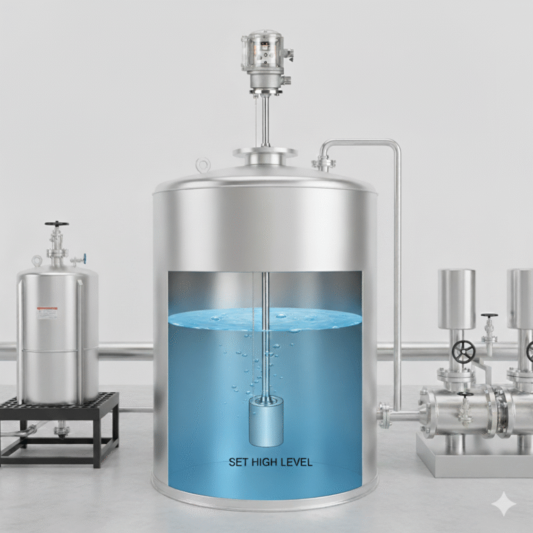
Buoyancy-type level instruments remain widely used across chemical processing, petroleum storage, water treatment and general industrial applications. Their stable performance, structural simplicity, and ability to operate in challenging process conditions make them a reliable solution for continuous or point-level measurement.
This article provides a structured overview of the most common buoyancy-type level devices, their operating principles, key components, accuracy-influencing factors, and differences between constant-buoyancy and variable-buoyancy designs.
1. Common Types of Constant-Buoyancy Level Instruments
Constant-buoyancy instruments rely on the principle that the float always stays on the liquid surface and moves proportionally (1:1) with the level change.
The most widely used types include:
1.1 Float Ball Level Gauge
This instrument operates on a mechanical lever system.
A hollow float ball is attached to one end of a lever, while a counterweight is attached at the opposite end, forming a torque-balanced mechanism. As the float rises or falls with the liquid level:
The lever rotates around its pivot point
This rotation drives a pointer for local indication
Or actuates microswitches for alarms
Or connects to a transmission mechanism that outputs pneumatic or 4–20 mA signals
Advantages:
Simple structure
Can accommodate a wide range of media conditions (temperature, pressure, viscosity)
Limitations:
Measurement range is limited by lever length and installation space.
1.2 Float-and-Tape (Float-and-Wire) Level Gauge
This type uses a float suspended on a stainless-steel tape or wire rope.
As the level changes, the tape moves correspondingly:
Direct mechanical connection can indicate the level locally
Or the tape movement can drive a pulley connected to a synchro transmitter, encoder, or other remote signal transmitters
Advantages:
Very wide measurement range (typically up to 25 m)
Suitable for large storage tanks (fixed roof tanks, floating roof tanks, spherical tanks)
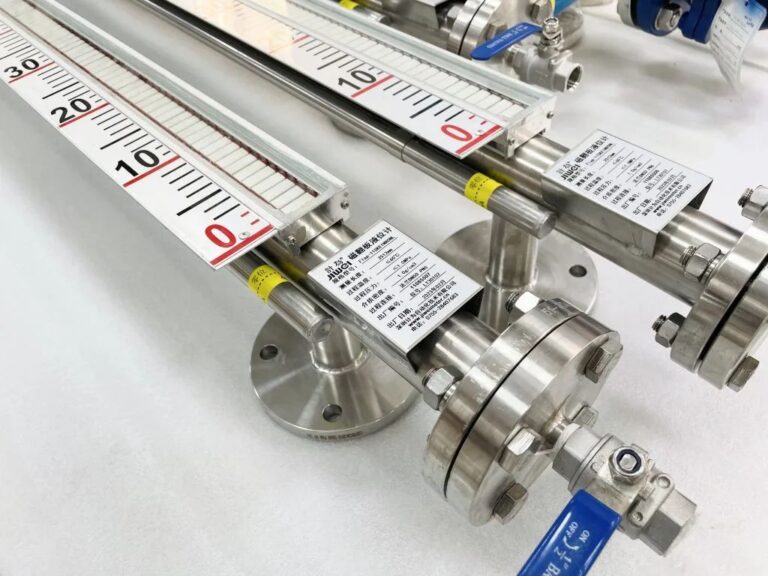
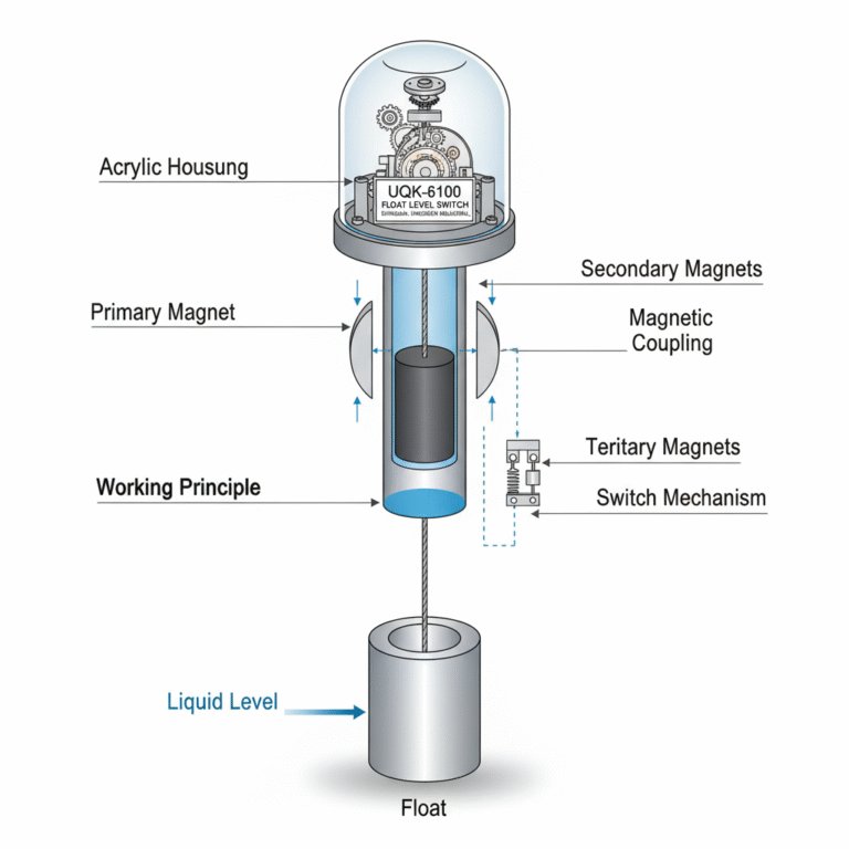
1.3 Magnetically Coupled Float Level Gauge (e.g., Magnetic Flip-Plate Indicator)
The float contains a permanent magnet.
As the float moves with the liquid level, the magnetic field drives external indication components via magnetic coupling, avoiding direct contact with the process medium.
A typical example is the magnetic flip-plate level indicator.
How the Flip-Plate Indicator Works
Each indicating plate consists of magnetic steel sheet coated red on one side and silver-gray on the other
Plates can rotate 180° around individual pivots
The float magnet flips the plates as it travels
Red indicates liquid, gray indicates vapor
Advantages:
Long measurement range
Works at high pressure
Highly visible indication
2. Accuracy Factors for Float-and-Tape Level Gauges
Float-and-tape gauges (also known as tank gauges) can achieve high accuracy:
±5 mm for level measurement
±2 mm for custody transfer or inventory measurement
However, several factors can affect accuracy:
Key influencing factors
Thermal expansion of the tape
Temperature changes cause length changes, significantly impacting measurement.
Example: A 10 m tape expands ~4.8 mm with a 30 °C temperature rise, and ~16 mm with a 100 °C rise.Float immersion depth variation
Caused by tape weight changes and density changes of liquid.Liquid density variation with temperature
Affects buoyancy and float position.Tank deformation
As the tank fills, shell expansion affects the effective volume.
Compensation methods
Mechanical compensation by adjusting hole spacing during tape perforation
Accuracy typically limited to 4–5 mm
Microprocessor-based automatic compensation
Best performance, accuracy up to ±1 mm
3. Common Types of Variable-Buoyancy Level Instruments
These instruments use a partially submerged displacer instead of a fully floating device.
The displacer experiences buoyancy changes as the liquid level changes, but its vertical displacement is very small.
Three primary designs exist:
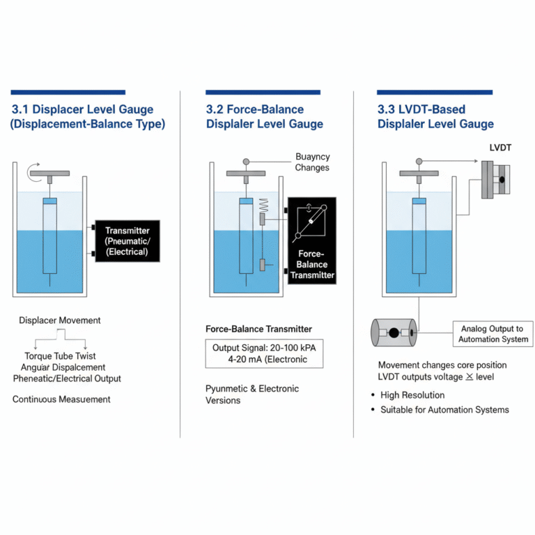
3.1 Displacer Level Gauge (Displacement-Balance Type)
The displacer movement causes a torque tube to twist
Angular displacement is converted into a pneumatic or electrical output signal
Suitable for process monitoring where continuous measurement is required.
3.2 Force-Balance Displacer Level Gauge
The displacer is suspended on the force-balance mechanism inside a pneumatic or electronic transmitter:
As buoyancy changes, the force balance shifts
The transmitter outputs a corresponding signal (pneumatic 20–100 kPa or electronic 4–20 mA)
Available in both pneumatic and electronic versions.
3.3 LVDT-Based Displacer Level Gauge
The displacer is connected to a magnetic or ferromagnetic core
Movement changes the position of the core inside an LVDT (Linear Variable Differential Transformer)
The LVDT outputs a voltage proportional to the liquid level
Advantages:
High resolution
Suitable for automation systems requiring continuous analog output
4. Key Differences: Constant vs. Variable Buoyancy Designs
| Feature | Constant-Buoyancy (Float Type) | Variable-Buoyancy (Displacer Type) |
|---|---|---|
| Buoyancy condition | Float is always on liquid surface | Displacer mostly submerged |
| Movement | Moves 1:1 with liquid level | Very small displacement |
| Typical instruments | Float ball, float-and-tape, magnetic flip-plate | Torque tube, force-balance, LVDT |
| Measurement range | Medium–large | Medium |
| Application | Storage tanks, simple process vessels | Process control, density-varying media |
| Signal output | Mechanical, magnetic, electrical | Pneumatic or 4–20 mA electronic |
Conclusion
Buoyancy-type level instruments remain essential in industrial level measurement thanks to their reliability, intuitive operation, and wide applicability.
Float-type (constant buoyancy) devices are ideal for storage tanks, visual indication, and large measurement ranges.
Displacer-type (variable buoyancy) devices offer better compatibility with process transmitters and automation systems.
Understanding their structure, accuracy factors, and operational differences allows engineers to make informed selections for various industrial environments.