Core Principle:
Temperature-related faults in electrical or industrial systems can be quickly located using the inherent resistance–temperature characteristics of NTC/PTC thermistors and the mV output characteristics of thermocouples.
By performing three diagnostic steps—static resistance check, dynamic heating/cooling test, and loop continuity/voltage measurement—more than 90% of temperature-related failures can be accurately identified.
1. Identify the Sensor Type First (Avoid Misdiagnosis)
| Sensor Type | Key Characteristics | Typical 25°C Value | Failure Estimation Logic |
|---|---|---|---|
| NTC Thermistor (home appliances, automotive) | Negative temperature coefficient: Temp ↑ → Resistance ↓ | 1kΩ / 5kΩ / 10kΩ / 50kΩ (e.g., “103” = 10kΩ) | ±30% drift → inaccurate reading; OL → open circuit; ≈0Ω → short circuit |
| PTC Thermistor (over-heat protection) | Positive temperature coefficient: Temp ↑ → Resistance ↑ sharply | Tens to hundreds of ohms | OL at room temp → open circuit; No resistance rise when heated → failure |
| Thermocouple (K/J type) | Generates mV signal; no fixed resistance | Loop resistance < 10Ω | No mV output → open circuit; mV deviation >50% → damage or wrong extension wire |
Quick Identification Tips:
NTC/PTC have a fixed resistance at room temperature.
Thermocouples do not—they show continuity but no stable resistance value.
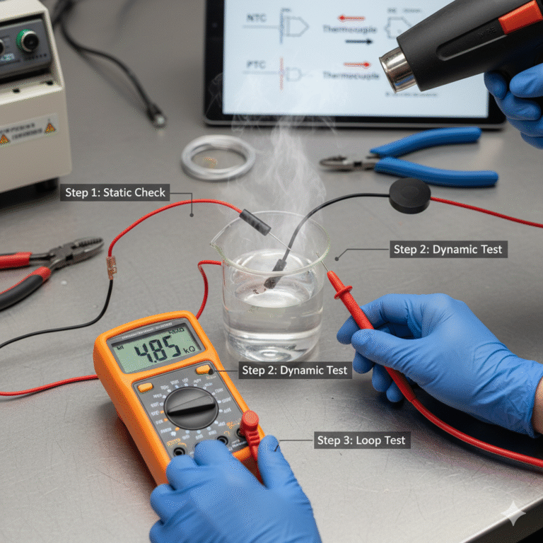
2. Three-Step Rapid Diagnosis Method
Step 1 — Static Room-Temperature Measurement (Identify drift/ open/ short quickly)
Power off and cool down the device to ensure the sensor returns to ~25°C.
Disconnect one lead of the sensor from the circuit to avoid interference.
Measure resistance using the correct multimeter range.
Interpretation:
Within ±10% of rated value → Sensor mostly OK; check wiring or controller.
Drift > ±30% (e.g., 10kΩ NTC showing 15kΩ or 5kΩ) → Sensor aging or drift.
OL / Infinity → Open circuit, broken wire.
Near 0Ω → Short circuit (NTC/PTC only).
Example:
A refrigerator NTC “103” reads 18kΩ at room temperature → drift → temperature reading too low → compressor may run continuously.
Step 2 — Dynamic Heating / Cooling Test (Check responsiveness)
Used when static resistance is “normal” but the device still behaves abnormally.
Heating methods:
Hold the sensor between fingers (≈35–40°C)
Low-temperature heat gun (≈50°C)
Warm water (for sealed sensors)
Cooling methods:
Electronic cooling spray
Ice pack (0–10°C)
Interpretation:
NTC Thermistor
Heat → Resistance must drop significantly (e.g., 10kΩ → 3–5kΩ)
Cool → Resistance should rise
No change = sensor failure
PTC Thermistor
When heated to 60–80°C, resistance should jump from tens of ohms to thousands
No sharp increase → faulty PTC
Thermocouple
Heat the hot junction → mV output must rise
K-type approx. 1.6 mV at 40°C
No mV change → open circuit or polarity reversed
Quick field trick:
Squeeze an NTC for 3 seconds:
Resistance ↓ by ≥50% = normal
No obvious change = faulty
Step 3 — Loop Continuity & Voltage Test (Identify wiring or controller issues)
If the sensor itself is normal, the fault is usually in:
1. Wiring / harness
Test continuity between sensor leads and controller terminals
Loop resistance should be < 1Ω
OL → broken wire or oxidized connector
2. Controller-side voltage
Many NTC sensors form a voltage divider. Measure sensor terminal voltage under power.
Interpretation:
Always 0V or full supply voltage → divider resistor open / short
Voltage fluctuates irregularly → controller input failure
Example:
An automotive coolant NTC (5kΩ) always reads full 12V → divider resistor on ECU is open → sensor is actually fine.
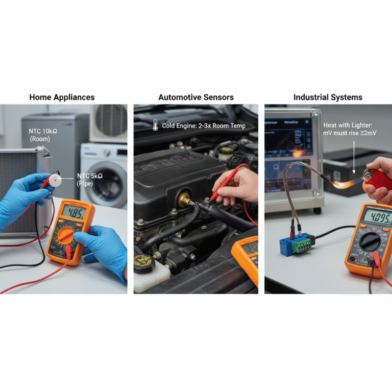
3. Application-Specific Diagnosis Tips
Home Appliances (AC, refrigerator, water heater)
Room sensor: NTC 10kΩ
Pipe sensor: NTC 5kΩ
±20% deviation → replace
Heating the sensor triggers compressor start/stop → sensor drift issue
Automotive Sensors (coolant, intake air)
Cold engine (0°C): Resistance should be 2–3× room-temp value
Hot engine (80°C): ≈1kΩ
No change → failed sensor
Wiring resistance >5Ω → connector corrosion
Industrial Systems (thermocouples)
Loop resistance <10Ω
K-type: 100°C ≈ 4.095 mV
Heat with lighter → mV rises by ≥2 mV
No rise → open circuit or wrong extension wire (very common)
4. Five Key Points to Avoid Misjudgment
Always measure resistance with power off.
Prefer measuring directly at sensor pins.
Understand NTC marking: “103” = 10 × 10³ = 10kΩ.
Meter ranges:
NTC: 20k / 200k range
PTC / wiring: 200Ω
Thermocouple: mV range
Diagnosis focuses on trend, not precise temperature (e.g., NTC must decrease when heated—if not, it’s faulty).