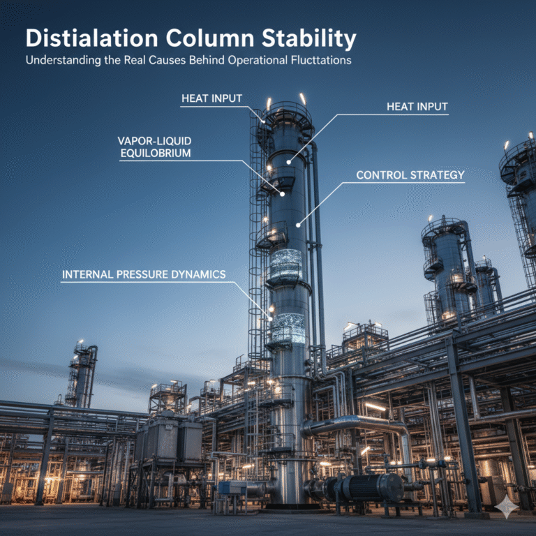
Distillation is often perceived as one of the simplest unit operations in chemical processing. In reality, a distillation column is a highly integrated thermal–hydraulic–mass transfer system whose stability depends on the precise interaction of heat input, vapor–liquid equilibrium, internal pressure dynamics, and control strategy.
When a column becomes unstable, operators are frequently blamed. However, most disturbances originate from equipment behavior, heat-integration mismatches, improper control loops, or upstream/downstream process interactions—not operator error.
This article provides a systematic technical explanation of distillation fundamentals, key equipment functions, commissioning logic, troubleshooting, and energy-optimization strategies, with practical insights from industrial experience.
1. Fundamentals of Distillation
Distillation relies on continuous phase contact between rising vapor and descending liquid across multiple theoretical stages. The essential mechanisms include:
Heat input at the reboiler to generate vapor.
Mass transfer between vapor and liquid on trays or packing.
Condensation of overhead vapor to provide reflux.
Internal counter-current flow that establishes concentration gradients.
A stable column maintains:
A monotonic temperature gradient (hot bottom → cold top).
Sufficient vapor flow to support tray loading or packing wetting.
Adequate liquid flow from reflux and feed distribution.
A steady internal pressure profile.
In chemical engineering terms, stability is achieved when heat transfer, mass transfer, and hydraulics remain in dynamic equilibrium.
2. Key Column Components and Their Operating Principles
2.1 Reboiler
The reboiler provides the driving force for separation by generating vapor.
Typical heating media include saturated steam, hot oil, or heat-pump systems.
Engineering characteristics:
The reboiler responds slowly; bottom temperature lags top temperature by 1–2 hours.
Excessive heat input increases vapor load, leading to flooding.
A rising reboiler duty without corresponding top-temperature drop may indicate fouling or heat-transfer degradation.
Operational focus:
Maintain stable bottom liquid level to avoid dry-out.
Monitor ΔT across the heater to detect fouling.
Prevent fast ramp-ups in steam pressure.
2.2 Trays and Packing
These are the core mass-transfer zones where vapor–liquid equilibrium is established.
Tray Columns (sieve, valve, bubble-cap):
Suitable for medium to high vapor loads.
Pressure drop and tray hydraulics are critical.
Packed Columns (random or structured):
Suitable for high-purity applications.
Highly sensitive to liquid distribution uniformity.
Field observations:
Uneven liquid distribution in packed columns reduces effective stages.
Sudden tray pressure drop increase suggests tray flooding, fouling, or mechanical damage.
“Cold start” without proper warm-up may cause thermal shock to packing.
2.3 Reflux System
Reflux controls liquid mass flow and determines internal stage efficiency.
General rule:
derived from McCabe–Thiele analysis.
Indicator behaviors:
Large overhead composition swings → reflux response lag.
Cyclic overhead temperature oscillation → cold-side control loop hysteresis.
High energy consumption with low bottom level → excessive reflux ratio.
3. Commissioning and Start-Up Logic
A controlled start-up is essential for stable long-term operation.
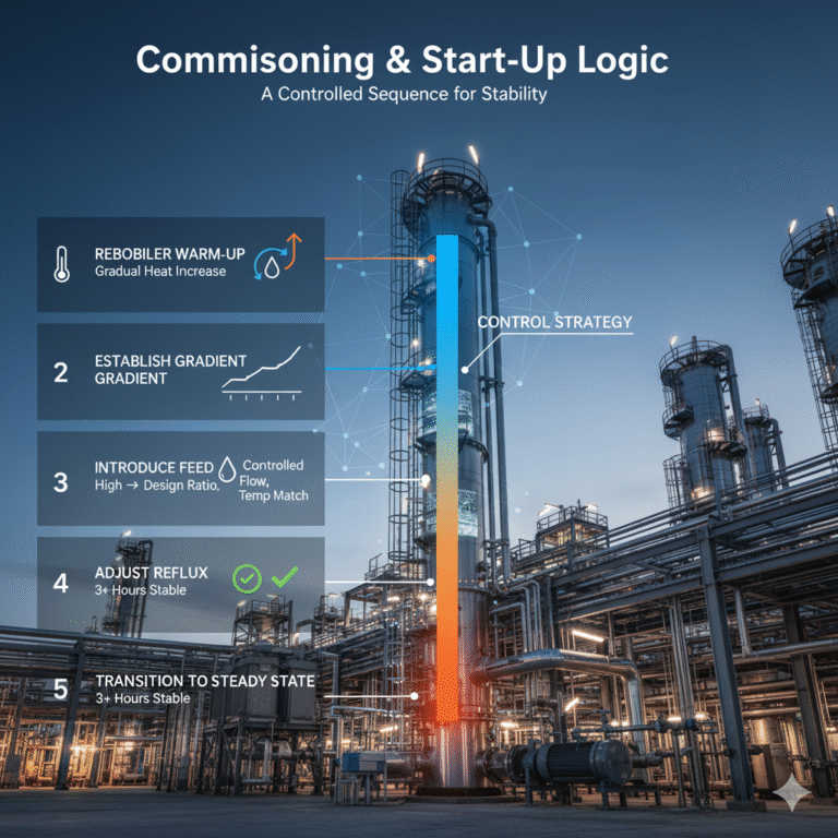
A typical sequence includes:
Step 1: Reboiler Warm-Up
Increase heating duty gradually (e.g., hold every 10°C for at least 10 minutes).
Avoid rapid pressure or temperature rise.
Step 2: Establish Temperature and Pressure Gradient
A healthy gradient is smooth and continuous.
“Reversed gradient” indicates internal condensation or maldistribution.
Step 3: Introduce Feed
Feed temperature should be close to the design feed condition determined by q-line analysis.
Cold feed shocks are a common cause of instability.
Step 4: Adjust Reflux Ratio
Start with high reflux, then slowly decrease to design level while observing overhead temperature and product analytics.
Step 5: Transition to Steady State
Operate for at least 3 hours of stable readings before considering the system in full equilibrium.
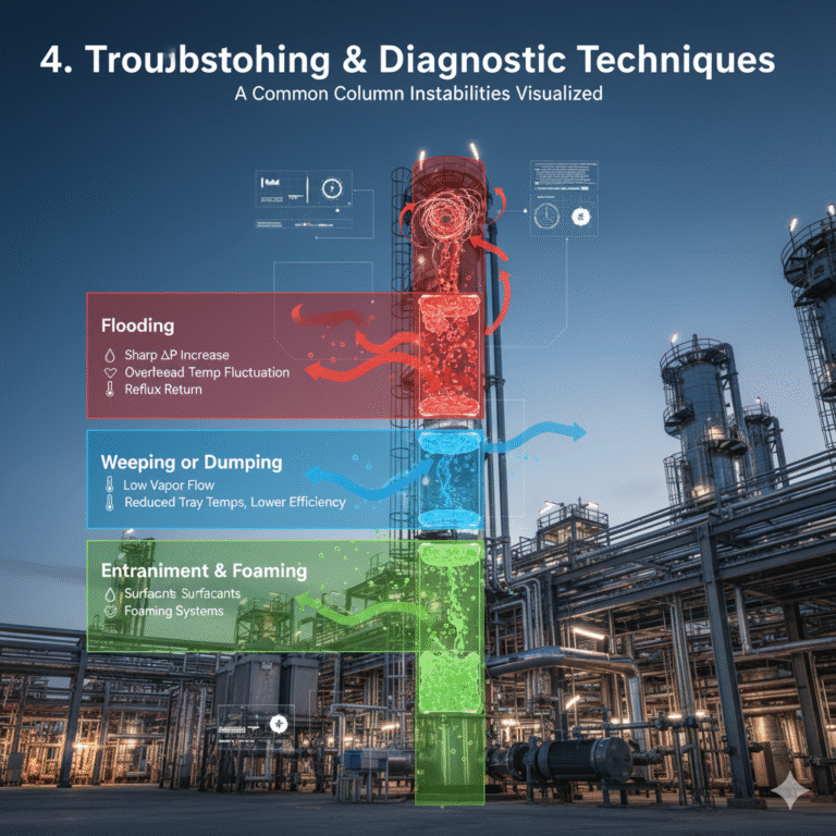
4. Troubleshooting and Diagnostic Techniques
4.1 Flooding
Symptoms:
Sharp increase in tray ΔP
Overhead temperature fluctuation
Reflux returning to the top section
Causes:
Excess vapor velocity
Excessive liquid load
Blocked trays or packing fouling
Corrective actions:
Reduce heat input
Check bottom level and reflux ratio
If necessary, lower operating pressure to reduce vapor load
4.2 Weeping or Dumping
Symptoms:
Vapor blows through trays
Reduced efficiency and lower tray temperatures
Causes:
Low vapor flow (insufficient reboiler duty)
Operating pressure too low
Corrective actions:
Increase reboiler duty
Stabilize column pressure
Adjust reflux distribution
4.3 Entrainment and Foaming
Symptoms:
Liquid carryover in overhead product
Analyzer abnormalities
Causes:
Surfactant presence
High vapor velocity
Excessive liquid level or foaming systems
Corrective actions:
Reduce liquid level
Reduce reboiler ramp rate
Apply antifoam if compatible with process
5. Strategies for Energy Optimization
5.1 Heat Integration
Use overhead condenser heat to preheat feed.
In multi-column systems, employ heat coupling.
Heat-pump distillation can yield up to 30% energy savings.
5.2 Pressure Optimization
Lower column pressure reduces boiling temperatures and steam consumption.
However, too low pressure increases vapor volume, potentially requiring larger column diameter.
Industrial practice favors moderate pressure reduction steps rather than a drastic pressure drop.
5.3 Advanced Control Strategies
Tight overhead temperature control
Reboiler duty with feed-forward compensation
Reflux ratio control based on combined PID + fuzzy logic
The industrial conclusion is clear:
energy savings come from precise heat-matching, not simply lowering steam usage.
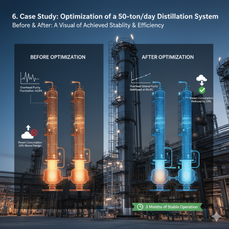
6. Case Study: Optimization of a 50-ton/day Ethanol Distillation System
A dual-column ethanol system (rectification + dehydration) showed:
Overhead purity fluctuation: ±0.8%
Steam consumption 20% above design
Optimization Steps
Analysis of overhead temperature & condenser pressure revealed unstable cooling-water temperature.
Reflux control changed from PID to ratio control to reduce hunting.
Reboiler heat redistributed using recovered heat from the overhead condenser.
Results
Overhead ethanol purity stabilized at 99.8%
Steam consumption reduced by 18%
Three months of stable, disturbance-free operation
Key takeaway:
Stability is achieved when heat flow, material flow, and pressure are dynamically balanced.
7. Conclusion
A distillation column is a highly dynamic chemical system—far more than a series of trays or a tall steel shell. The interaction between mass transfer, heat transfer, pressure dynamics, and process-control behavior determines whether a column remains stable or oscillates.
By applying systematic commissioning, diagnostic reasoning, and energy-optimization strategies, engineers can significantly improve product stability, reduce energy consumption, and extend equipment life.
Distillation reliability is not achieved by “more heat” or “more reflux,” but by managing the internal balance of vapor, liquid, and heat with precision.