Thermocouple compensation cables play a critical role in temperature measurement systems. They extend the thermocouple signal from the sensing point to the control room while maintaining measurement accuracy. Selecting the correct compensation cable ensures stable signal transmission, reduces cold-junction influence, and minimizes measurement error.
This guide explains how to correctly identify different types of compensation cables (K, S, E, etc.), how to distinguish polarity, how to recognize genuine vs. counterfeit cables, and how to choose the right cable for industrial applications.
1. What Is a Thermocouple Compensation Cable?
A compensation cable is a pair of conductors made from materials that have similar thermoelectric characteristics to the thermocouple within a limited temperature range.
Purpose
Extends the thermocouple wires to move the cold junction away from heat sources
Minimizes temperature gradients at the connection points
Maintains accuracy of the millivolt-level signal
Improves system stability in long-distance wiring
If the cable does not match the thermocouple type (e.g., using K-type cable on an S-type thermocouple), large errors will occur.
2. Naming Rules of Compensation Cables (Example: KX, SC, BC)
Compensation cables are typically marked with two letters:
(1) First Letter – Thermocouple Type
K → Nickel-Chromium / Nickel-Silicon
S → Platinum-Rhodium / Platinum
B → Platinum-Rhodium 30 / Platinum-Rhodium 6
E → Nickel-Silicon / Copper-Nickel
(2) Second Letter – Cable Type
X → Extension type (same materials as thermocouple)
C → Compensation type (similar thermoelectric characteristics but different alloy)
Example
SC = Compensation cable for S-type thermocouple
BC = Compensation cable for B-type thermocouple
KX = Extension cable for K-type thermocouple
3. How to Identify K-Type, S-Type, and Other Compensation Cables
3.1 By Color Code (International Standard IEC 60584)
| Thermocouple | Positive Wire | Negative Wire | Overall Jacket |
|---|---|---|---|
| K (NiCr–NiSi) | Yellow | Red | Yellow or Green |
| E (NiSi–CuNi) | Purple | Red | Purple |
| S (PtRh10–Pt) | White | Red | White |
| B (PtRh30–PtRh6) | Gray | Red | Gray |
Note: Actual colors may vary by region, but polarity always follows:
Red = Negative (N) in IEC standards.
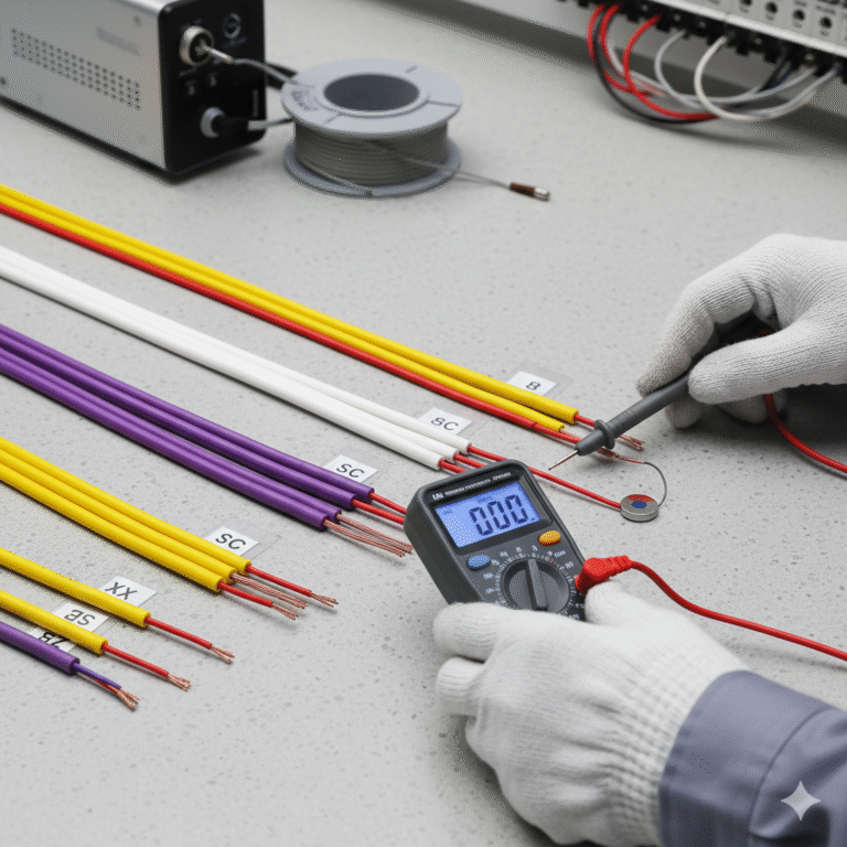
4. Engineering Method to Distinguish K-Type and S-Type Cables
Color is not always reliable (especially in the Chinese domestic market). The most accurate method is to check the material characteristics of the negative conductor:
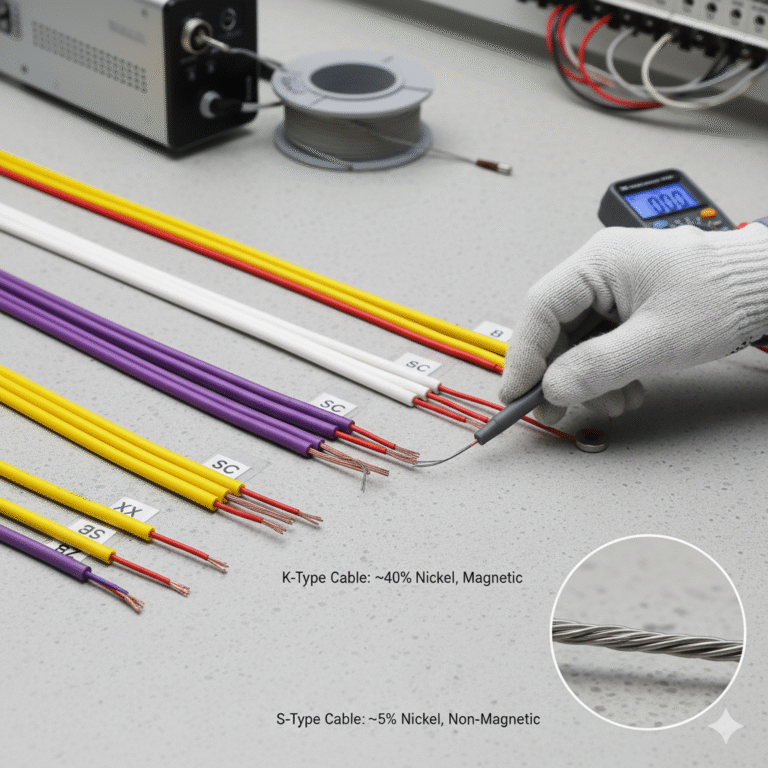
K-Type Compensation Cable
Negative conductor contains ~40% nickel
Material is relatively hard
Shows slight magnetic attraction
Suitable for general industrial use (−20°C to 200°C)
S-Type Compensation Cable
Negative conductor contains ~5% nickel
Material is softer and less magnetic
Used for high-temperature platinum-rhodium thermocouples
Common in metallurgy, furnaces, and high-precision labs
Extension Cable Difference
KX uses the same material as K-type thermocouple
KC uses alternative alloys with similar EMF characteristics
Comparing with the thermocouple wire itself helps identify extension vs. compensation type
5. Differences Between SC and BC Compensation Cables
| Code | Thermocouple Type | Material Characteristics | Application |
|---|---|---|---|
| SC | S-type | Alternative alloys for PtRh/Pt | 0–200°C extension to control rooms |
| BC | B-type | Alternative alloys for PtRh30/PtRh6 | High-temperature furnace monitoring |
These cables cannot be used interchangeably, as the thermoelectric properties are different.
6. How to Identify Genuine vs. Counterfeit Compensation Cables
6.1 Correct Cable Selection
Choose cable that matches the thermocouple type and operating temperature.
Example for K-type:
Standard range: −20°C to 100°C
Extended range: −25°C to 200°C
Accuracy class:
Standard grade: ±2.5°C
Precision grade: ±1.5°C
6.2 Polarity and Connection
Keep both thermocouple terminals at the same temperature
Avoid placing junctions near cooling fans or heat sources
Ensure tight and corrosion-free connections
6.3 Cable Length
Thermocouple signals are very weak (microvolt-level).
Recommended compensation cable length: ≤ 15 meters
If longer: use a temperature transmitter (4–20 mA) to avoid noise and signal loss
6.4 Cable Routing
Keep away from power cables and electromagnetic interference
If crossing is unavoidable, use 90° crossing, not parallel routing
6.5 Shielded Compensation Cable
Use shielding in noisy environments
Shield must be grounded, otherwise interference may increase
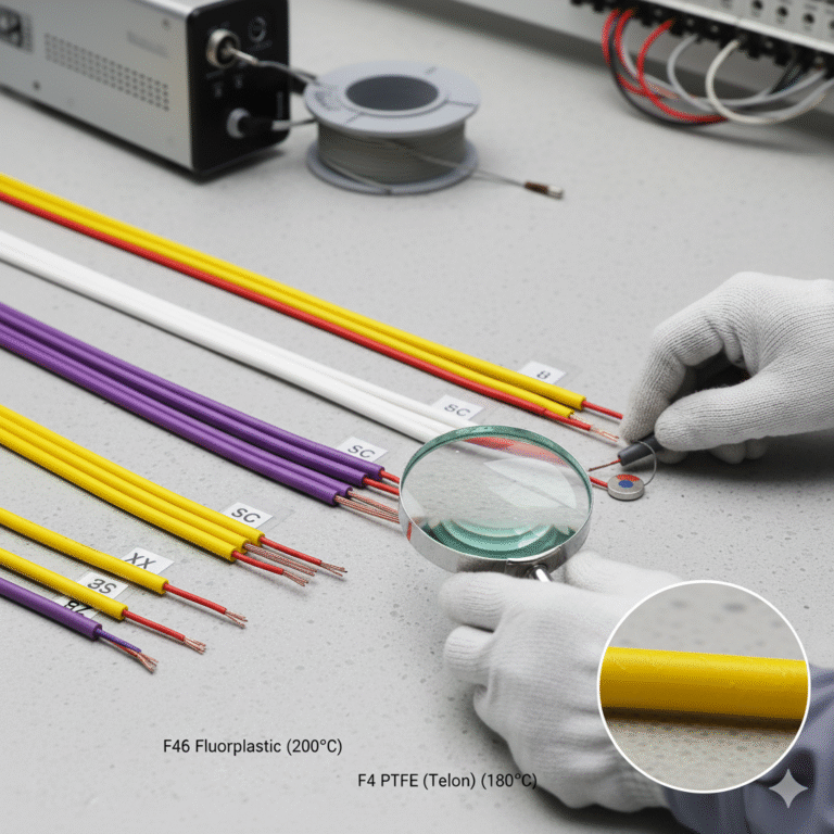
7. Special Notes on Cable Materials (F46 vs. F4 Sheath)
Used commonly in K-type cables:
| Model | Material | Temperature Rating |
|---|---|---|
| F46 | Fluoroplastic | 200°C |
| F4 | PTFE (Teflon) | 180°C |
Choose the insulation according to ambient temperature and installation conditions.
8. Summary and Best Practices
Always match the compensation cable with the thermocouple type (K, S, B, E).
Verify polarity: red wire is always negative in IEC systems.
Limit cable length to 15 m; use transmitters for longer distances.
Use shielded cables in high-interference areas.
Ensure proper grounding and avoid parallel routing with power cables.
Select insulation based on temperature and chemical resistance.
For high-temperature platinum-rhodium thermocouples (S/B type), use corresponding SC/BC cables only.
Correct cable selection and installation directly affect temperature accuracy and equipment reliability.