When a new industrial plant or production unit is ready for commissioning, the instrumentation system plays a crucial role in ensuring safe startup and stable operation. Any mistakes in installation, wiring, calibration, or control logic may lead to inaccurate measurement, poor control performance, equipment damage, product quality issues, or even safety incidents.
This article provides a practical and comprehensive pre-startup instrumentation checklist, covering design verification, installation inspection, loop checking, control logic testing, and operational readiness. It is designed for instrumentation engineers, commissioning teams, EPC contractors, and plant operations personnel.
1. Verify Technical Documents and Design Consistency
Before checking physical equipment, always ensure that the documentation is complete, correct, and consistent with the field installation.
Key Items to Confirm:
P&ID and Actual Installation Match
Instrument tag numbers, process tapping points, signal direction, and interlock logic must align.
Technical Datasheets and Certificates
Device specifications: measuring range, accuracy grade, material compatibility, process pressure and temperature limits.
Calibration certificates and quality inspection records.
Explosion-proof and environmental protection ratings.
Control and Interlock Logic Files
DCS/PLC/SIS configuration matches design intent.
No missing or additional logic points.
Field Cable and Tubing Routing
Cable types, grounding method, tube material, and installation path comply with design.
A correct and updated documentation baseline prevents troubleshooting difficulties later during startup.
2. Inspect Instrument Hardware and Installation Quality
Even correctly selected instruments may fail if installation is improper. Conduct a thorough physical inspection before powering up.
2.1 Instrument Hardware Condition
Tags, models, and ranges comply with datasheets.
Materials are compatible with process fluids (e.g., diaphragm, lining, wetted parts).
Explosion-proof and ingress protection levels meet area classification.
No visible damage, corrosion, deformation, or loose electrical glands.
Check for noise or instability (fluctuation ≤ ±0.1 mA).
Digital Communication (HART / Modbus / Profibus)
Confirm device addresses are unique.
Check baud rate, termination resistance, and network stability.
Be sure diagnostic and parameter reading can be accessed via control system.
Discrete Inputs and Outputs (DI/DO)
Switches actuate at correct setpoints.
DO commands operate actuators and feedback returns accurately.
This step ensures the signal chain is continuous, correct, and stable.
4. Validate Interlock and Control Logic Functions
Instrumentation not only measures processes―it also protects the plant. Therefore, interlock logic must be tested before introducing live process conditions.
Validate:
Interlock trigger conditions (e.g., high pressure → pump trip).
Alarm display and event recording.
Bypass and reset functions work as designed.
Redundant control modules switch over smoothly without loss of function.
PID loops are tuned for stable control response:
No excessive overshoot (≤ 5%)
Stable final control value with minimal oscillation
This ensures safe system response during process disturbances.
5. Check Supporting Systems
Instrumentation performance relies on supporting utilities:
Instrument Air System
Pressure stable at 0.4–0.6 MPa.
Air must be clean, dry, and oil-free.
No leaks at fittings or actuator diaphragms.
Heat Tracing and Insulation
Prevent freezing or condensation in impulse lines.
Uniform heating and intact insulation wrapping.
Grounding and Lightning Protection
Signal ground and protective ground separated.
Grounding resistance meets standard requirements.
6. Conduct Cold and Hot Commissioning
Cold Commissioning (No Process Fluid)
Verify motor and valve actuation.
Confirm stable signal and control behavior.
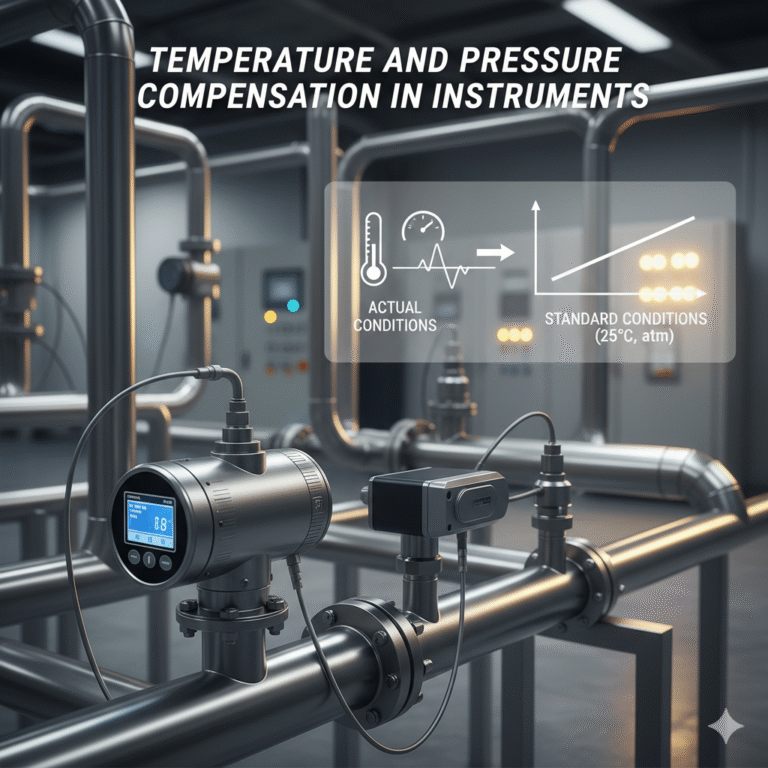
Hot Commissioning (With Process Fluid)
Monitor accuracy under real operating temperature and pressure.
Log behavior and fine-tune control loops.
Observe for drift, vibration, or signal interference.
Conclusion
A well-executed pre-startup instrumentation verification program ensures:
Accurate and stable process monitoring
Reliable and responsive control loops
Safe equipment operation and interlock protection
Reduced risk during initial startup and long-term operation
This checklist helps build a strong foundation for plant reliability from day one.