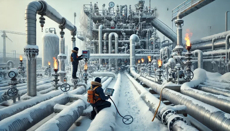
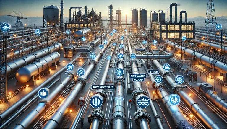
Electric heat tracing systems are widely used in chemical, petrochemical, coal-to-chemicals, refining, and water treatment industries to prevent pipeline freezing, maintain process temperature, and ensure stable plant operation during cold weather. Based on heating characteristics and construction, heat tracing cables are mainly classified into:
Each type features different temperature capabilities, installation requirements, investment levels, and maintenance characteristics.
2. Self-Regulating Heat Tracing Principle
The core heating element of a self-regulating heat tracing cable is a PTC (Positive Temperature Coefficient) conductive polymer. The electrical resistance increases as the temperature rises, automatically reducing output power. This allows the system to adjust heat output according to ambient and pipe temperature without external control.
Working Process
Cold Start
At low temperatures, resistance decreases
Startup current is relatively high (typically 1.5–2.5 times rated current)
Temperature Stabilization
As the pipe warms up, resistance increases
Current decreases accordingly
Heat output automatically stabilizes
Dynamic Self-Adjustment
When ambient temperature drops again, the cable automatically increases heat output
Ensures continuous anti-freezing and temperature maintenance
This self-regulating mechanism prevents overheating, enhances safety, and reduces energy consumption.
3. Why Tripping Occurs During Sudden Temperature Drop
Common Field Observation
When ambient temperature falls below approximately −5°C, certain heat tracing circuits may trip intermittently.
Root Causes
Cause
Explanation
Higher Startup Current in Cold Conditions
Low temperature reduces conductor resistance, increasing inrush current
Delayed Current Attenuation
More heat loss to environment slows warm-up, extending high-current period
Breaker Thermal Protection Activation
Sustained high current heats the breaker bimetal element, triggering trip
Key Insight
This phenomenon is not due to cable failure, but due to prolonged current plateau, not just a short current spike.
4. Field Factors That Increase Tripping Risk
Damaged or waterlogged insulation layer → Rapid heat loss
Circuits designed too close to the breaker capacity limit
Use of C-type breakers instead of recommended D-type breakers for high inrush loads
Large pipeline surface area / heavy wind exposure
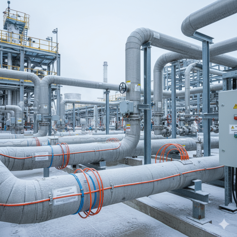
5. Installation and Critical Details
Heat Tracing Application Methods
Method
Application
Notes
Linear Installation
Standard pipelines
Ensure full surface contact and consistent fixing
Spiral Winding
Large diameter or high heat demand
Maintain uniform pitch, avoid excessive tension
Overlapping (Self-regulating only)
Valves, pumps, flanges
Constant wattage cables must not overlap to avoid overheating
Tail End Treatment (Critical for Reliability)
The tail end must be sealed with certified termination kits
Conductors must not be shorted
In hazardous areas, Ex-rated junction box and termination kits are mandatory
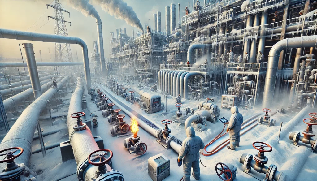
6. Winter Inspection and Maintenance Guidelines
Routine Operation Checkpoints
Inspection Item
Method
Acceptance Criteria
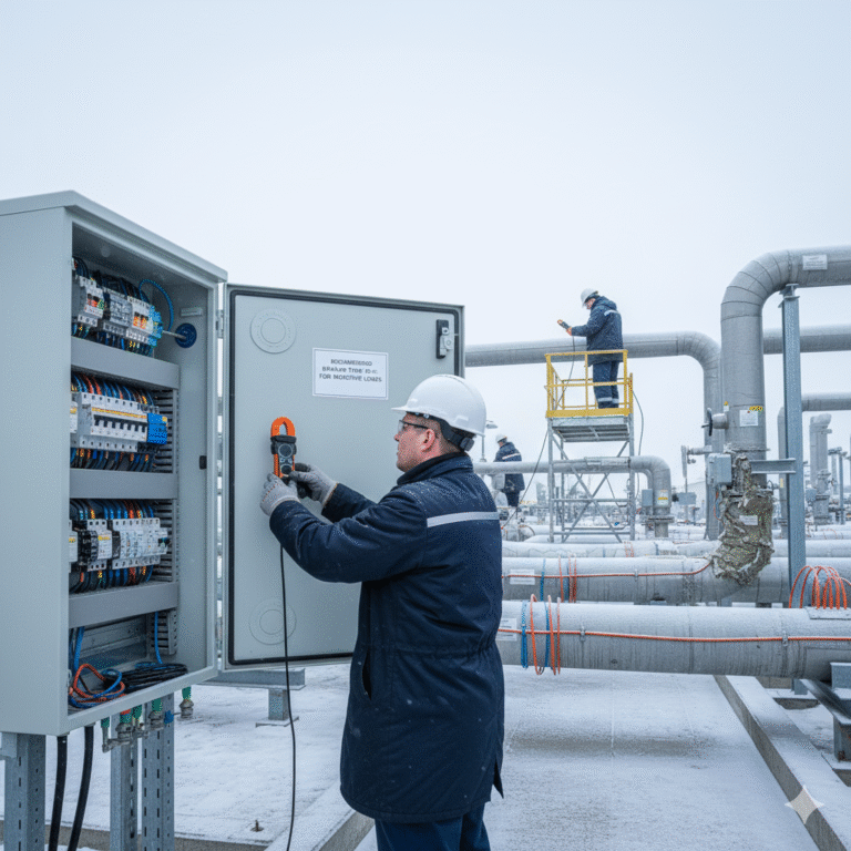
Operating Current
Clamp meter measurement
Stable and within design value
Surface Temperature
Touch or IR thermometer
Uniform heating, no noticeable cold spots
Junction Boxes
Visual inspection
Dry, sealed, no condensation or corrosion
Special Inspection During Cold Weather
Increase inspection frequency during nighttime and early morning
Focus on previously problematic circuits
Repair damaged insulation immediately to avoid heat loss amplification
7. Solutions to Frequent Tripping
Problem Scenario
Recommended Corrective Action
Frequent trips during temperature drop
Replace C-type breaker with D-type breaker
Circuit load near rated limit
Split circuit or increase power supply segmentation
High heat loss or damaged insulation
Repair / retrofit insulation layer
Aging or incorrect connectors
Replace with certified termination kits
8. Conclusion
Self-regulating heat tracing is a critical safeguard for winter operation in industrial facilities. Understanding its temperature-electricity interaction, ensuring proper installation, and implementing systematic inspection and maintenance are key to preventing winter-related failures such as circuit tripping and pipeline freezing.
A well-managed heat tracing system directly contributes to: