Have you ever stood in front of the large screen in a control room, watching numbers and flashing symbols, but had no idea what they meant? Don’t worry! This article will help you understand the soul of factory automation—control loops.
What is a Control Loop?
In industrial control systems (DCS/PLC), each control loop functions like a nerve in the human body. It consists of three core components: the measurement element, the controller, and the actuator.
Measurement Element: The “Eyes” of the System
Its task is to observe reality. It monitors changes in process parameters like temperature, pressure, level, and flow. On a PID diagram, you’ll see them represented as LT (Level Transmitter), FT (Flow Transmitter), TT (Temperature Transmitter), and PT (Pressure Transmitter).
For example:
When the level in a tank drops to 45%, the LT-1001 transmitter informs the system, “The level is too low!”Controller: The “Brain” of the System
The controller receives data from the sensors, compares it with the setpoint (SP), and then issues commands. On a PID diagram, you’ll see controllers such as LIC (Level Controller), FIC (Flow Controller), TIC (Temperature Controller), and PIC (Pressure Controller).
The second letter “I” or “C” indicates that it’s part of an automated control system (BPCS).Actuator: The “Hands and Feet” of the System
These components execute commands from the controller, adjusting valve positions or pump speeds. On a PID diagram, you’ll find symbols such as LV (Level Valve), FV (Flow Valve), and TV (Temperature Valve), often with a positioner, which ensures precise control—much like the muscles of the system.

The Three Key Variables: SP, PV, OP
Understanding these three terms is crucial to interpreting most DCS displays.
| Term | Meaning | Example |
|---|---|---|
| SP (Set Point) | The desired target value | “I want the level to stay at 50%” |
| PV (Process Value) | The current actual value | “The level is currently at 45%” |
| OP (Output) | The system’s action to adjust | “The valve is set to 65% to add liquid” |
Control logic is similar to everyday scenarios:
“I want my weight to stay at 60kg (SP) → The scale shows 62kg (PV) → Reduce food intake (OP)”
Now it makes sense, right?
How to Identify a Control Loop?
In P&ID Diagrams:
Symbols like LIC-101, TIC-201 indicate an automated control loop with SP, PV, and OP variables.On the DCS Screen:
SP and PV are often shown on trend graphs, while OP represents the current valve position or pump speed.
Operation Tip:
Before changing the SP in the DCS, make sure to switch the control mode from AUTO to MANUAL. Otherwise, the system won’t let you interfere.
Bringing a Control Loop Online
Let’s take the example of a Level Control Loop (LIC-1001). The key to bringing it online is: “Switching without causing erratic valve movement or process fluctuations.”
Steps to Bring the Control Loop Online:
Ensure the Equipment is Normal: Verify that transmitters and valves are free of alarms.
Set the Controller to Manual (MAN): Make fine adjustments to OP until the level stabilizes near the current value.
Set SP to the Current Level (PV): When PV equals SP, the output stabilizes. Then, switch to AUTO mode.
Fine-tune SP to the Desired Target Value: Allow the controller to take over and maintain the level.
This process is like driving a car: first, you stabilize the steering wheel before activating the cruise control.

When to Switch Out of Auto Mode?
Even the most advanced systems can malfunction. A switch-out from automatic to manual may occur in the following cases:
Controller Failure: Inaccurate measurements or controller failure.
Significant Process Disturbance: Large fluctuations or instability in the process.
Startup/Shutdown: For manual control during these phases.
Maintenance: When isolating instruments for repair.
Switch-out Steps:
Identify the Problem: If the level or flow fluctuates significantly, or if the controller indication is abnormal, immediately switch to manual (MAN).
Manually Adjust the Valve: Stabilize the process and notify the maintenance team.
In Emergency Situations: You can press the “hard manual” button to stop the system from making any automatic adjustments—safety first!
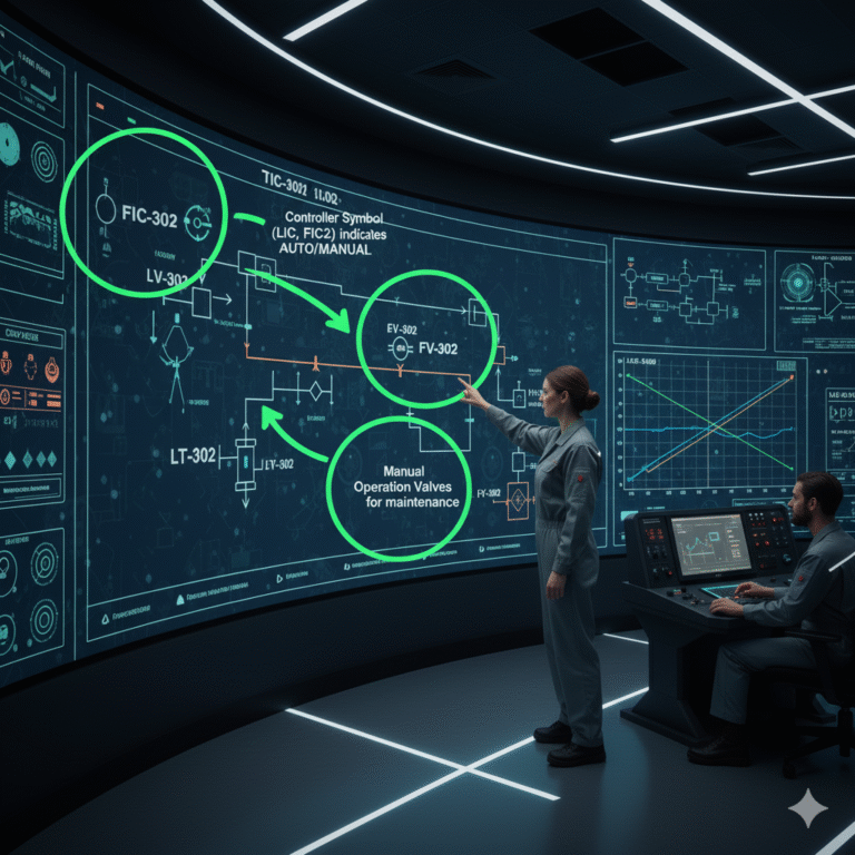
Identifying Manual Operation Capability on Diagrams
The controller symbols (like LIC, FIC) indicate the ability to switch between manual and automatic modes.
Small circles next to control valves represent manual operation wheels on-site.
Bypass lines near the main line, equipped with manual valves, allow continued operation during maintenance.
Conclusion
Mastering this control loop logic allows you to easily “read the system” on a factory floor. From level control to pressure, temperature, and flow, the control loop is the heartbeat of a factory’s automation system.
Next time you see symbols like “LIC-1001” or “TIC-2003,” they won’t seem so mysterious anymore, will they?