The installation and commissioning of radar level gauges are not particularly complex but require strict adherence to guidelines to avoid measurement errors—especially when dealing with high-viscosity or high-temperature media, such as asphalt. The key to success lies in attention to detail, such as installation location and probe calibration. The overall process can be divided into four steps: “Preparation → On-site Installation → Basic Commissioning → Process Adaptation.” Below are the challenges and key points for each step:
1. Installation Process: Moderate Difficulty – Focus on “Obstacle Avoidance and Interference Prevention”
The core of the installation process is ensuring that the radar waves are unobstructed and free from strong interference. While the steps are clear, attention to detail is essential:
Choosing the Installation Location (Most Critical)
Ensure the probe is placed away from obstacles inside the tank, such as mixers, heating coils, and ladders. Maintain at least 30 cm from the tank wall (or 1/6 of the tank diameter, whichever is greater) to avoid false echoes caused by obstructions. For asphalt tanks, special care is needed. If the tank has a vent valve or feed inlet at the top, the probe should avoid the material drop area (as asphalt splashes may contaminate the probe or create foam interference). It is recommended to keep the probe at least 1.5 meters away from the inlet.
Vertical Installation: The probe should be level. Tilted probes may cause radar wave reflection errors. Tighten the threaded or flange connections to prevent loosening due to high temperatures.
Mechanical Installation (Simple)
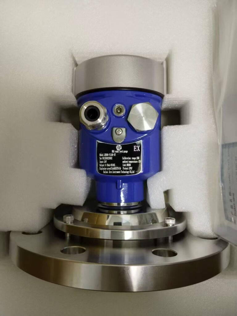
Most radar level gauges use flanged or threaded connections, which can be directly connected to the pre-installed interface on the tank top. No special tools are needed (wrench or sealing tape will suffice). For high-temperature models, confirm that the seals are suitable for high temperatures (e.g., fluororubber seals for temperatures above 200°C) to avoid leakage or aging.
Wiring (Standard Industrial Practices)
Separate power (typically 24V DC) and signal cables (4-20mA or HART) to avoid electromagnetic interference. In areas with strong interference sources (e.g., motors), shielded cables should be used with one-end grounding. For asphalt tanks, use high-temperature cables (e.g., silicone rubber cables, rated for temperatures above 180°C).
2. Commissioning Process: Low Difficulty – Guided by the Instrument’s Menu
Modern radar level gauges are typically intelligent models, allowing easy commissioning through buttons or handheld devices (such as HART375), without the need for professional programming skills:
Basic Parameter Settings (Essential)
Enter tank parameters such as tank height (distance from probe to tank bottom when empty) and dead zone (area below the probe where measurements are not taken, typically 5-30 cm; for asphalt tanks, set it to ≥ 10 cm to avoid interference from bottom residue).
Medium parameters: Asphalt’s dielectric constant (typically >3). High-frequency radar is not sensitive to the dielectric constant, but guided-wave radar requires accurate input to ensure strong reflection signals.
Echo Curve Calibration (Core Step)
The instrument automatically collects the echo curve (displaying the radar wave’s emission and reflection patterns). Ensure that the “real liquid level echo” is clear and of high strength (amplitude > 50%), with no significant interference echoes from the tank wall or obstacles.
If there are interference echoes, use the “false echo suppression” feature to ignore the affected areas (manually mark the interference spots). This is particularly important for asphalt tanks, where volatile substances may condense on the probe’s surface. Confirm that the probe is unobstructed.
Accuracy Verification (Simple)
When the tank is empty, the instrument should show a value close to the “tank height” (error ≤ ±5mm). When the tank is full or the liquid level is known (e.g., using a manual dipstick), compare the actual level and fine-tune the “zero” or “range” parameters as needed.
3. Special Considerations for Asphalt Tanks (To Avoid Future Troubles)
Clean the Probe Before Installation
Ensure the probe surface is free from oil or dust to prevent initial signal attenuation.
High-Temperature Adaptation
During commissioning, confirm that the instrument’s “high-temperature mode” is enabled (some models require manual setup to avoid triggering temperature protection due to high heat).
Regular Maintenance Reminder
Although radar level gauges are non-contact and low-maintenance, it’s recommended to check the probe every three months to ensure it’s free from fouling (as asphalt vapors may deposit on the probe). If fouling is found, clean the probe with a soft cloth soaked in solvent (avoid scratching the probe surface).
Conclusion
For individuals with experience in industrial instrument installation, setting up and commissioning a radar level gauge can be completed within 1-2 hours. The process is less complicated than with servo or differential pressure level gauges, which require complex mechanical structures or density calibrations. The main challenges lie in “avoiding installation obstacles” and “interpreting the echo curve.” However, manufacturers typically provide user manuals and technical support, so even beginners can quickly become proficient.