The installation of the pressure tapping for throttling devices may seem simple, but it directly affects the accuracy of the measurement. This is especially critical when measuring steam flow on vertical pipelines, where the correct positioning of the tapping is key. However, in many cases, pressure tapping systems designed for aesthetics sacrifice signal transmission accuracy, leading to noticeable low or unstable readings, especially at low flow rates.
Why Do Small Installation Differences Lead to Significant Measurement Errors?
The role of the pressure tapping system is to transmit the differential pressure signal generated by the throttling device to the differential pressure transmitter without distortion. However, in practical applications, the configuration of pressure tappings is often problematic.
One of the most serious issues occurs in vertical pipelines used for steam flow measurement. To maintain signal integrity, the pressure tapping system should adhere to a specific structure, as shown in the figure below.
According to GB/T 2624-2006, which specifies the requirements for differential pressure flow meters, the pipeline should ideally be horizontal. However, in real-world applications, vertical pipelines are unavoidable. Therefore, a structure such as the one shown in the figure below is required to preserve signal accuracy.
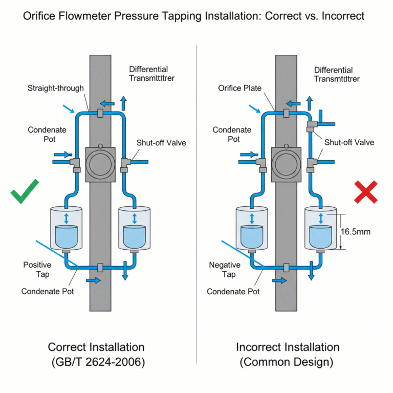
Correct Installation for Proper Signal Transmission
In the correct design, the shut-off valve is a straight-through valve (e.g., gate or ball valve). As long as the condensate end of the pressure tapping pipe is slightly higher than the throttling device end, the condensate will flow back into the main pipeline smoothly. This setup ensures that the liquid levels in both condensate chambers remain equal, allowing steam to flow normally into the upper part of the condensate chambers, ensuring correct steam-liquid exchange.
Unfortunately, many flowmeter manufacturers provide a design like the one shown in the second figure. While this setup looks aesthetically pleasing, it compromises its primary function.
Incorrect Pressure Tapping Setup: Unstable and Low Flow Readings
In the second design, although the condensate can flow freely back from the positive pressure tapping pipe to the main pipeline, the negative pressure tapping pipe will not drain properly until the liquid inside the pipe accumulates. This results in inconsistent liquid levels between the two condensate chambers. For instance, if the liquid height in the negative pressure chamber is the same as the left end of the tapping pipe, the liquid column height will be about 16.5mm higher in the negative pressure chamber compared to the positive pressure one, due to the 33mm distance between the two openings.
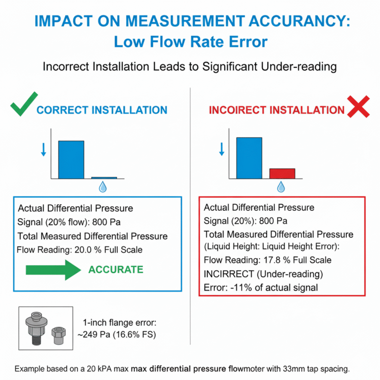
Impact on Measurement Accuracy
This incorrect installation leads to substantial measurement errors, especially at low flow rates. For example, in a differential pressure flowmeter with a maximum pressure differential of 20kPa, at 20% of the full scale (qm = 20% of qmmax), the signal from the throttling device would be 800Pa. If an additional differential pressure of 165Pa occurs due to the liquid height discrepancy in the condensate chamber, the flowmeter reading would decrease to 17.8% of full scale.
For installations where 1-inch flanges are used for pressure tapping, the error increases due to the larger distance between the tapping ports. The additional differential pressure might be around 249Pa, causing the flow reading to drop to 16.6% of full scale.
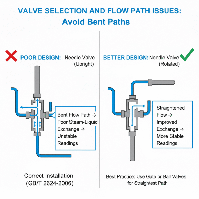
Valve Selection and Flow Path Issues
A common valve choice for pressure tapping systems is the needle valve. However, with the valve handle pointed upwards, the flow path becomes bent, leading to poor steam-liquid exchange. This inconsistency in the liquid level height causes instability in readings, particularly at low flow rates.
Some users may rotate the valve handle to a horizontal position, turning the previously bent flow path into a more straightforward route. This can improve steam-liquid exchange and reduce errors. In some documents, it is recommended to use gate or ball valves, as they have larger passages and do not pose concerns for steam-liquid exchange due to their straight flow paths.
Conclusion: The Importance of Correct Installation
From real-world usage, it has been observed that when the flow rate is around 10% of full scale, the readings stabilize as expected when the correct valve and pressure tapping installation is used. Proper pressure tapping installation ensures more accurate and stable readings across various flow conditions. Therefore, it is essential to ensure that the design and installation of pressure tappings are done according to the specific requirements, to avoid unnecessary deviations and ensure reliable flow measurement.