1. Overview of Temperature and Pressure Compensation
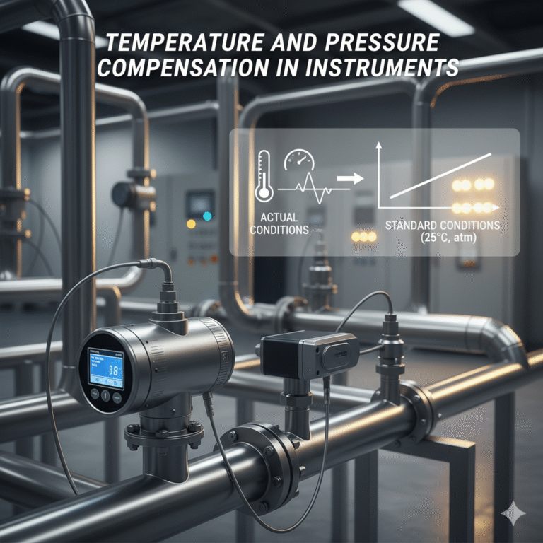
Temperature and pressure compensation is a technique used to automatically adjust the measurement results of instruments to standard conditions, specifically 25°C and 1 standard atmosphere pressure. This is done by measuring the actual temperature and pressure on-site and using a compensation formula to convert the readings to standard conditions. The core purpose of this technology is to convert measurements under non-standard conditions to corresponding values at standard conditions, ensuring comparability across different measurement points for easier comparison and statistics.
2. Types of Instruments Requiring Temperature and Pressure Compensation
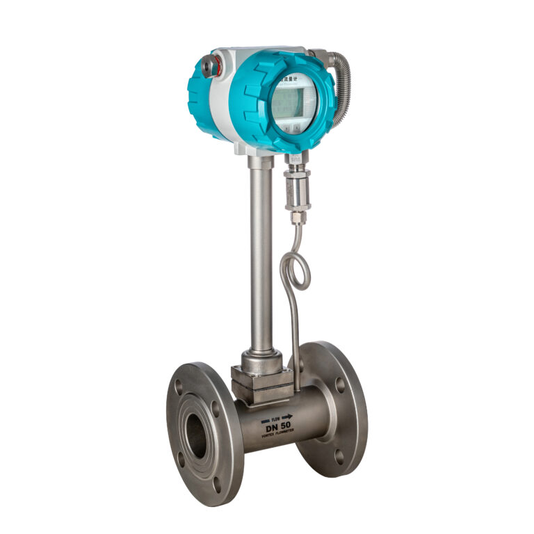
2.1 Vortex Flow Meters
Applications: Used to measure the flow of gases, steam (both saturated and superheated), and liquids.
Compensation Reason: Fluid density changes with variations in temperature and pressure, affecting measurement accuracy.
Features: Equipped with built-in temperature probes and external pressure transmitters, forming an integrated temperature-pressure compensation system.
Applicable Media: Compressed air, steam, and others.
2.2 Differential Pressure Flow Meters
Types: Orifice flow meters, Venturi meters, Annubar meters, etc.
Compensation Reason: These meters measure volume flow under current working conditions, which must be converted to mass flow at standard conditions.
2.3 Gas Turbine Flow Meters
Compensation Reason: The density of gases is significantly influenced by temperature and pressure, requiring compensation to convert volume flow to standard mass flow.
2.4 Flow Totalizers
Function: Dedicated flow measurement and totalization systems designed for temperature and pressure compensation.
Input Signals: Temperature, pressure, and flow (current, voltage, or pulse signals).
Applications: Measurement of superheated steam, saturated steam, and general gas flows.
3. Methods of Temperature and Pressure Compensation
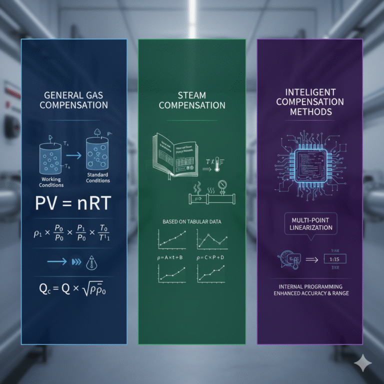
3.1 General Gas Compensation
Based on the ideal gas law:
This leads to the density compensation formula:
Where:
-
= Gas density at working conditions (
)
-
= Standard gas density (
)
-
= Standard atmospheric pressure (0.1013 MPa)
-
= Working pressure (absolute pressure, MPa)
-
= Standard temperature (293K or 20°C)
-
= Working temperature (absolute temperature, K)
Flow Compensation Formula for Differential Pressure Flow Meters:
After compensation:
Where:
-
= Compensated flow
-
= Measured flow
-
= Differential pressure
-
= Instrument coefficient
3.2 Steam Compensation
For steam (both superheated and saturated), compensation is based on tabular data and linear interpolation methods:
-
Compensation Principle: Based on the “Water and Steam Property Handbook” for steam properties.
-
Compensation Range:
-
Superheated steam: Pressure (0.1–16) MPa (gauge), Temperature (140–560)°C
-
Saturated steam: Pressure (0–16) MPa (gauge)
-
Linear compensation formulas:
-
Temperature compensation:
-
Pressure compensation:
Where
,
,
, and
are linear coefficients calculated from actual working conditions at two data points.
3.3 Intelligent Compensation Methods
Modern instruments use multi-point linearization compensation techniques:
-
Principle: Internal programming is used to perform multi-point linearization compensation of flow signals.
-
Advantages: Ensures measurement accuracy at every point within the flow range, with a range ratio of up to 1:15 (compared to the typical 1:5 for regular vortex flow meters).
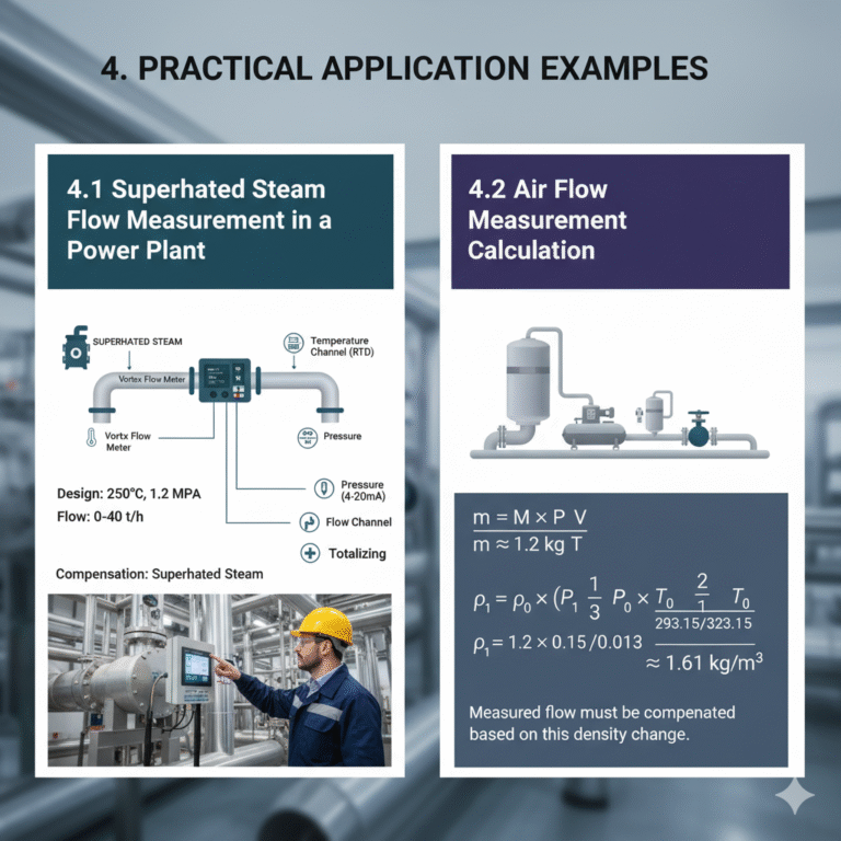
4. Practical Application Examples
4.1 Superheated Steam Flow Measurement in a Power Plant
Design Conditions:
Temperature: 250°C
Pressure: 1.2 MPa (gauge)
Differential Pressure Range: 0-30 kPa
Flow Range: 0-40 t/h
Instrument Configuration:
Temperature Channel: Type: Resistance temperature detector (RTD), Unit: °C, No square-rooting, No compensation
Pressure Channel: Type: 4-20mA standard signal, Unit: MPa, No square-rooting, No compensation
Flow Channel: Type: 4-20mA (differential pressure transmitter output), Range: 0-40 t/h, No square-rooting, Totalizing: Yes, Compensation: Superheated steam
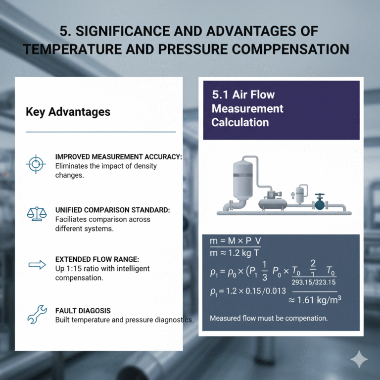
4.2 Air Flow Measurement Calculation
For calculating the standard air mass:
Where:
= Air molar mass (29 g/mol)
= Standard atmospheric pressure (101325 Pa)
= Volume (1 m³)
= Gas constant (8.314 J/(mol·K))
= Standard temperature (293.15 K)
After calculation:
For changes in temperature and pressure, the density compensation is:
The measured flow must be compensated based on this density change.
5. Significance and Advantages of Temperature and Pressure Compensation
Improved Measurement Accuracy: Eliminates the impact of density changes caused by temperature and pressure fluctuations on flow measurements.
Unified Comparison Standard: Converts all measurements to standard conditions, facilitating comparison and statistical analysis across different systems.
Extended Flow Range: Intelligent temperature and pressure compensation can expand the range ratio up to 1:15, 3 times higher than traditional instruments.
Fault Diagnosis: Built-in temperature and pressure fault diagnostics improve system reliability.
6. Considerations
6.1 Suitable Applications
Applications with minimal temperature and pressure requirements
Compressed air measurement
Internal measurement scenarios
6.2 Limitations
Higher maintenance costs
Data retrieval may need to be done from the flow meter’s display
Not suitable for suspended pipeline applications
6.3 Installation Requirements
Temperature and pressure measurement points should be close to the flow measurement point
Ensure measurement synchronization