With the rise of Industry 4.0, smart manufacturing, and digital twin technologies, PLCs (Programmable Logic Controllers) have evolved from traditional logic controllers to core control units capable of data processing and intelligent decision-making. They not only determine the “operation logic” of production lines but also support the safety, stability, and scalability of entire automation systems.
This article delves into the top 10 core areas of PLC knowledge, helping engineers progress from “using PLCs” to truly “understanding control systems.”
1. PLC Working Principles and Development Trends
PLC is essentially a specialized control computer for industrial environments. It works by using a scan cycle, which includes three phases:
Input Sampling: Collect signals from sensors and buttons.
Program Execution: Perform calculations based on programmed logic.
Output Refresh: Send control signals to actuators.
This continuous cycle allows PLCs to respond to real-time changes in milliseconds, ensuring system reliability and real-time performance. Today, PLCs are evolving into smart controllers, integrating AI algorithms, remote diagnostics, and cloud communication capabilities. These advancements pave the way for edge computing and IIoT (Industrial Internet of Things) architectures in the future.

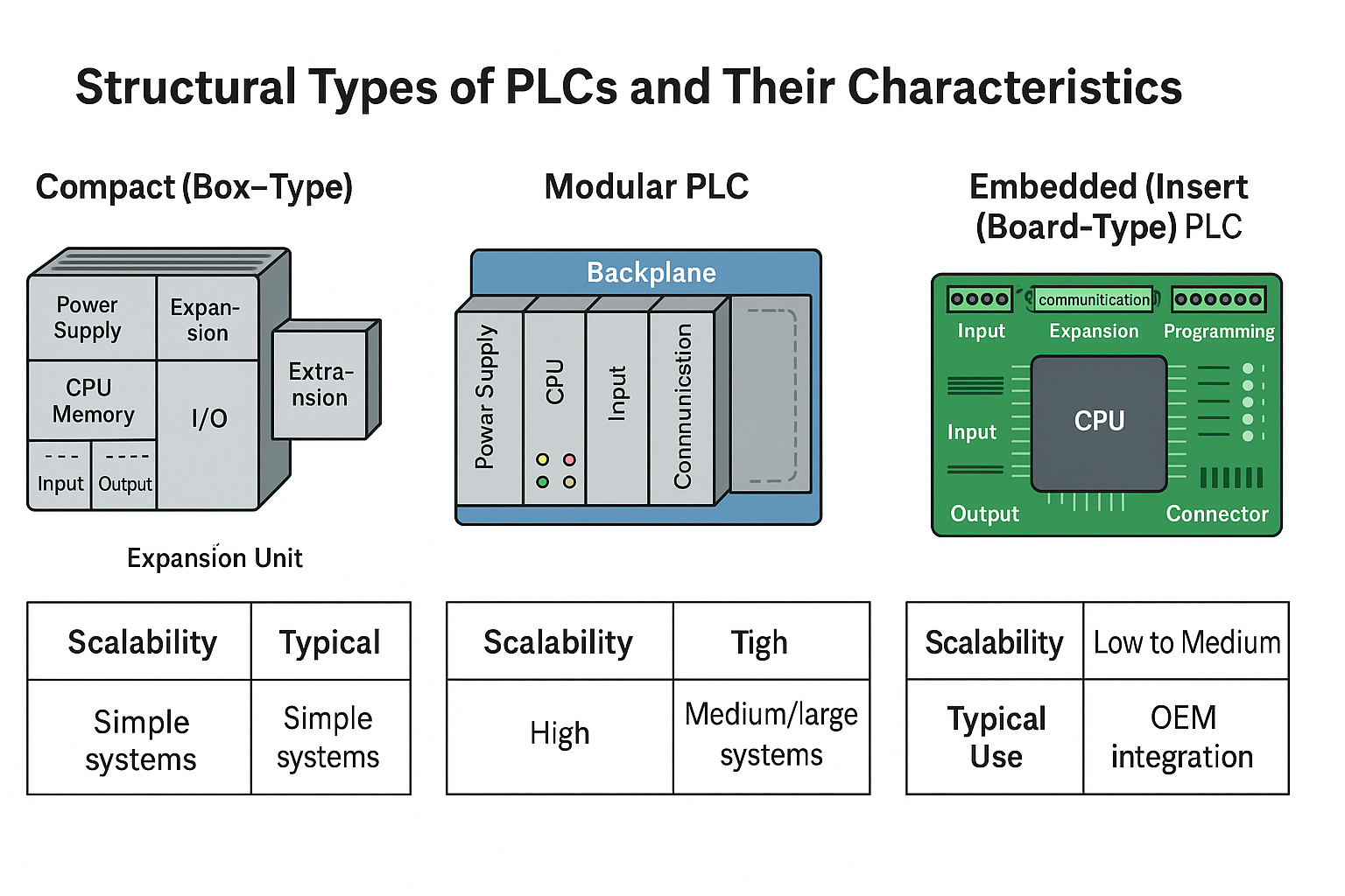
2. Understanding PLC Modules and Architecture
A standard PLC system typically consists of several key modules:
CPU (Central Processing Unit): Performs logical and arithmetic operations and data communication.
Input Modules (DI/AI): Collect digital and analog signals.
Output Modules (DO/AO): Control actuators such as relays, motors, and valves.
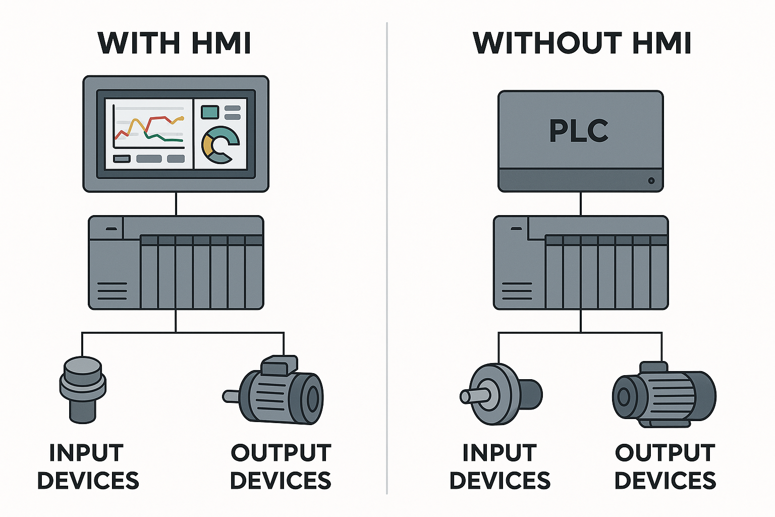
Communication Modules: Enable data exchange with higher-level systems, frequency converters, and HMIs.
Power Supply Module: Provides stable voltage to prevent electromagnetic interference.
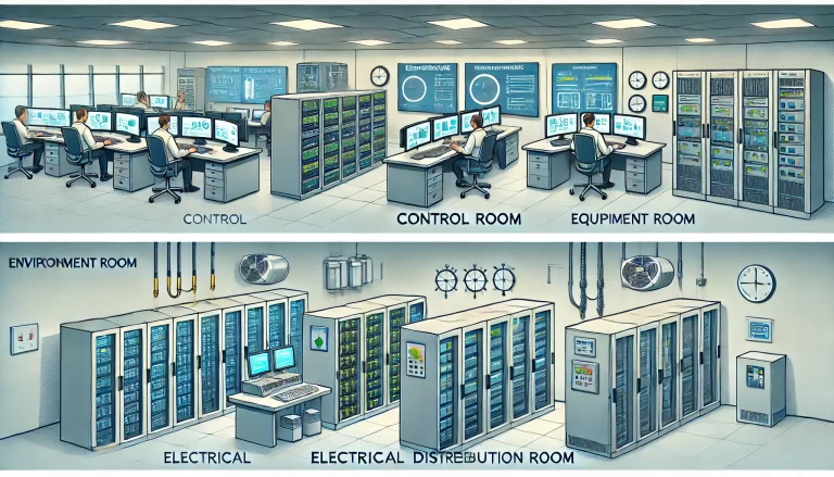
In distributed control systems (DCS), PLCs connect with remote I/O via field buses, forming a multi-layer control structure. It is recommended to strictly separate high-voltage and low-voltage circuits during control panel wiring to avoid electromagnetic interference that could cause malfunction.
3. The Five PLC Programming Languages and Logical Thinking
According to the international standard IEC 61131-3, five programming languages are used for PLC programming, each corresponding to different logical thinking modes:
| Language | Features | Typical Applications |
|---|---|---|
| Ladder Diagram (LD) | Similar to relay circuits, easy to read and maintain | Mechanical control, electrical interlocks |
| Function Block Diagram (FBD) | Graphical structure, clear logic | Continuous process control, PID |
| Structured Text (ST) | Similar to C language, suited for complex calculations | Mathematical models, algorithm logic |
| Instruction List (IL) | Assembly-like, high execution efficiency | Small PLCs, embedded control |
| Sequential Function Chart (SFC) | Hierarchical flow control | Multi-step process flows |
For complex projects, a mix of languages is often used: main logic with LD, complex algorithms with ST, and sub-functional modules with FBD, achieving both visualization and maintainability.
4. I/O Systems and Signal Wiring Key Points
The I/O modules of PLC serve as the bridge to the real world, and correct wiring and debugging are crucial to system stability:
Digital I/O (DI/DO): Reflects on/off status of devices.
Analog I/O (AI/AO): Collects and outputs continuous signals such as temperature, pressure, and current.
Signal Isolation and Protection: Use optocouplers, filtering capacitors, and surge suppressors to enhance anti-interference.
Grounding and Shielding: Employ single-point grounding and layered shielding to ensure signal integrity.
In high-speed production line projects, grounding errors often lead to false triggers or communication failures. When designing systems, prioritize separating “signal ground” and “protective ground.”
5. Communication Protocols and Industrial Networks
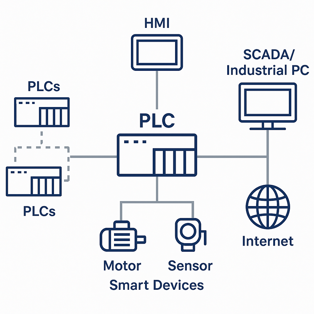
PLCs are no longer isolated units but are deeply embedded in complex industrial communication networks, acting as core nodes for data exchange and intelligent control. Different communication protocols form the language system of this network:
Modbus RTU/TCP: Widely used for interconnecting devices from different brands due to its openness and ease of deployment.
Profibus/Profinet: Dominates in Siemens systems.
EtherNet/IP: Known for high bandwidth and real-time response, commonly used in high-speed control scenarios.
CANopen/DeviceNet: Excellent for motion control, robotics, and embedded systems.
OPC UA: With cross-platform and cloud communication capabilities, it’s becoming the key protocol connecting field devices with cloud systems.
In the future, industrial communication will move toward unification, openness, and cloud collaboration. PLCs will transition from “control executors” to “data acquisition and intelligent decision-making frontiers.”
6. Advanced Applications of Timers and Counters
Timers and counters are basic functions of PLCs, yet they can be used to create complex logic in engineering:
TON/TOF/TP Timers: Achieve delayed start, stop, and pulse output.
CTU/CTD/CTUD Counters: Perform product counting, event detection, and cycle statistics.
Timed Interrupt Tasks: Enhance response speed via interrupt mechanisms.
Time Synchronization: Sync with network clocks or higher-level systems to ensure consistency across systems.
In packaging production lines, PLCs use CTU counters to trigger automatic production batch switching, achieving full-cycle production management.
7. PLC System Fault Diagnosis and Maintenance
A true PLC expert not only knows programming but also masters troubleshooting logic. Common diagnostic methods include:
Checking CPU status and I/O indicators.
Analyzing error codes via diagnostic buffers.
Monitoring real-time variable states.
Using the force function to test hardware circuits.
Inspecting communication interruptions and loose connections.
Tools like Siemens TIA Portal and Schneider EcoStruxure support “trend monitoring,” which tracks variable changes in real-time, a powerful tool for debugging complex systems.
8. Program Optimization and Real-Time Management
PLC programs need to run not only correctly but also efficiently and stably. Key optimization strategies include:
Reducing nested logic and repeated calls.
Properly assigning task priorities (main tasks, cyclic tasks, interrupt tasks).
Optimizing scan cycles.
Using local variables instead of global ones.
Adding watchdogs and timeout protection mechanisms.
For large filling systems, task-level optimization reduced cycle time from 50ms to 15ms, improving system response by over 200%.

9. Safety Protection and Emergency Control
In industrial automation, safety design always takes precedence over logic optimization. PLCs should have the following safety mechanisms:
Hardware Protection: Emergency stop circuits, safety relays, and dual-channel redundancy.
Software Logic: Interlock control and fail-safe design.
Functional Safety Standards: Compliance with IEC 61508 and ISO 13849.
Emergency Mechanisms: Power-fail hold, power-off self-check, and remote alarms.
For example, in automotive welding production lines, if communication is interrupted, the PLC immediately cuts off the robot’s drive power, ensuring SIL2-level safety shutdown.
10. Standardization and Future Trends
Mastering standards is the foundation for advancing to system-level engineering. Relevant standards include:
IEC 61131-3: Defines PLC programming languages and execution models.
IEC 61508/ISO 13849: Specifies functional safety systems.
IEC 62443: Industrial control system network security standards.
OPC UA and MQTT: Pushing for PLC-cloud integration.
The future of PLCs will involve integration with AI control algorithms, digital twins, and edge computing, creating intelligent control systems capable of predictive maintenance, adaptive optimization, and remote collaboration.
Conclusion
Mastering the top 10 core PLC knowledge areas means not only knowing how to program but also having a system-level mindset. When you understand the principles behind control logic, communication architecture, and safety mechanisms, you elevate yourself from an “electrical engineer” to an “automation system architect.” In the future, competition in manufacturing will not be about who has the bigger equipment, but who has the smarter control, more efficient systems, and more valuable data.