In the world of PLC programming, most engineers are familiar with Ladder Diagram (LAD) and Structured Text (ST or SCL).
These two have dominated the automation field for decades due to their intuitive representation and widespread support.
However, the IEC 61131-3 standard defines five programming languages for PLCs—and among them lies a powerful yet often overlooked one:
the Sequential Function Chart (SFC).
SFC isn’t new, but with the growing demand for modular design and visual control, it’s making a strong comeback among industrial automation engineers.
What Is SFC (Sequential Function Chart)?
SFC, also known as State Transition Diagram or Functional Chart, is a graphical programming language specifically designed for describing sequential control processes in PLC systems.
It provides a structured and visual way to represent automation logic—making each step, transition, and condition explicit.
SFC is one of the five standard PLC programming languages defined by IEC 61131-3, alongside:
Ladder Diagram (LD)
Function Block Diagram (FBD)
Instruction List (IL)
Structured Text (ST)
The core idea of SFC is simple yet powerful:
To make the execution sequence of a control system visible through graphical states and transitions.
This allows complex logic to be broken down into clear, modular “steps” that are easy to read, debug, and maintain.
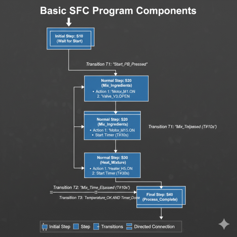
Basic Components of an SFC Program
An SFC program is composed of several key building blocks, each serving a distinct function in defining the process logic.
1. Steps
Each step represents a specific operating state of the system.
Initial Step – The starting condition of the process (e.g., waiting for a start command).
Normal Step – Intermediate or running states during the process.
Inside each step, engineers can define actions, such as turning on a motor, opening a valve, or calling a function block.
2. Transitions
Transitions determine when and how the system moves from one step to another.
A transition is triggered when a predefined condition (sensor signal, timer completion, flag bit, etc.) becomes true.
3. Directed Connections
These lines connect steps in a logical sequence—usually from top to bottom.
Although the arrows can sometimes be omitted, the direction of logic flow must always be clear.
4. Actions and Commands
Each step may include associated operations like:
Start/stop motors
Open/close valves
Reset counters
Execute subroutines
In other words, SFC steps are not just visual elements—they represent real actions in the process.
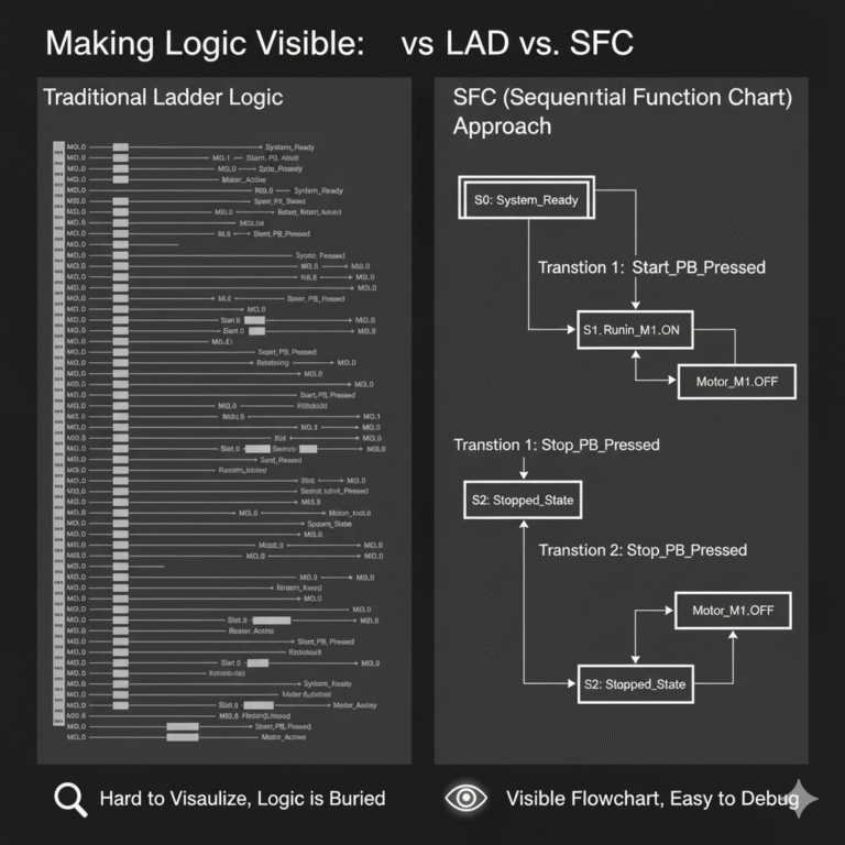
Why Use SFC? Making Logic Visible
Many engineers already apply sequential logic in Ladder or ST programming without realizing it.
Typical approaches include:
Relay logic using multiple memory bits (M0–M100) to represent different states.
Step programming using internal flags like S0–S100.
Register method where numeric values (e.g., D10, D20) indicate current operation stages.
These approaches work, but the logic is buried deep in code—making it hard to visualize or troubleshoot.
SFC, on the other hand, turns this logic into a visible flowchart.
It displays the entire control process—from Start → Run → Stop → Reset—in a single visual structure.
When debugging, you can immediately see which step is active and where the process stopped.
This visibility dramatically reduces maintenance time and simplifies communication between engineers.
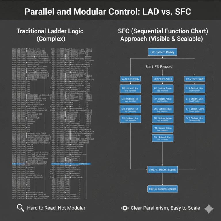
Real-World Application: Parallel and Modular Control
Let’s look at a simple yet common example.
Suppose you have a PLC system controlling three independent workstations, each capable of manual or automatic operation.
When the system enters automatic mode, it should follow this sequence:
Press Start → All three stations run simultaneously
Press Stop → All stations stop together
Press Reset → System returns to initial state
Traditional Programming Approach
In Ladder or ST, you might:
Use M0–M399 to represent each state,
Define S0–S399 for each step,
Or assign D registers (D10, D20, D30) for each station’s phase.
While functional, this approach quickly becomes complex and hard to maintain, especially as the project grows.
SFC Approach
With SFC, you can create three parallel branches, each representing one workstation.
Each branch operates independently but can be synchronized by top-level control signals (Start, Stop, Reset).
This graphical structure provides:
Clear logic hierarchy
Easy debugging
Simple scalability (adding a new station requires just another branch)
SFC makes multi-station and multi-mode control far more manageable.
Key Advantages of SFC
✅ Clear Logical Structure
Each process is divided into distinct steps and transitions—easy to understand at a glance.
✅ Easy Debugging & Maintenance
The current active step is visually displayed, simplifying fault diagnosis.
✅ Supports Parallel and Branch Logic
Perfect for complex systems involving multiple operations running simultaneously.
✅ Standardized under IEC 61131-3
Ensures high compatibility across different PLC platforms (Siemens, Omron, Schneider, Beckhoff, etc.).
✅ Improved Team Collaboration
SFC diagrams are intuitive even for non-programmers, making it easier to communicate with mechanical, electrical, and process engineers.
When Should You Use SFC?
SFC is ideal for:
Sequential or batch processes (filling, heating, mixing, cleaning)
Multi-station or modular control systems
Equipment with frequent mode changes (auto/manual)
Processes requiring clear visual representation for maintenance or safety audits
In essence, if your process can be described as a sequence of actions and conditions, SFC is a perfect fit.

Conclusion: From Electrical Thinking to System Thinking
In the evolving world of industrial automation, clarity and modularity are everything.
While Ladder Diagrams extend the traditional electrical thinking,
SFC represents a shift toward system thinking—where logic, visualization, and structure work hand in hand.
By mastering SFC, you’re not just learning another PLC language—you’re adopting a way to design, visualize, and manage control systems more intelligently.