In industrial automation, the coordination between the valve stroke and positioner is critical for accurate control. Although butterfly valves inherently have a 90° rotational stroke, setting this value to 90° in some positioners can lead to mismatches and errors. This article explores why this happens and how to address the issue.
Understanding the Feedback Mechanism and Rotation Mismatch
The key to this issue lies in the feedback mechanism of the positioner and how it interacts with the valve’s rotational stroke. A butterfly valve’s 90° angle of rotation must be converted into a feedback signal that the positioner can understand. If the connecting parts, such as linkages or feedback arms, are not correctly matched, this conversion process can fail, leading to incorrect positioner readings.
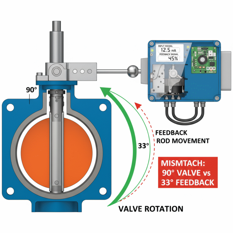
For example, when the valve rotates 90°, the linkage may only cause the feedback rod to move 33°, resulting in a mismatch. If the positioner is set to 90°, it will think the valve hasn’t moved to its correct position and continue sending control signals, potentially leading to over-travel, alarm activation, or control failure.
1. The Feedback Logic of the Positioner:
The positioner’s core function is “closed-loop control.” It uses an input signal (e.g., 4-20 mA) to move the valve and simultaneously senses the actual valve position through the feedback rod. The positioner compares the feedback signal with the input signal to correct any discrepancies.
Here’s the key point: the positioner tracks the movement of the feedback rod, not the valve itself. In a properly matched system, when the valve rotates 90°, the feedback rod should also rotate 90° (1:1 ratio). However, if the connection components are misaligned (such as an incorrectly sized feedback arm or linkage), the feedback rod may only rotate 33°, creating a ratio mismatch (about 2.7:1). In this case, the positioner will continue to drive the valve, mistakenly thinking it hasn’t reached the correct position.
2. The “33° Linear Stroke” Concept
When we suggest using a “33° stroke” setting for the positioner, it refers to the feedback rod’s actual movement. While the valve still has a 90° rotary stroke, the feedback mechanism is designed to move in a linear-like fashion when the angle is small (less than 45°). In this case, the positioner needs to be calibrated based on the actual movement of the feedback rod (33°) rather than the full 90° stroke of the valve.
In simpler terms: the positioner’s stroke parameters must follow the feedback rod’s movement. If the feedback rod can only move 33°, the positioner should be calibrated to that range. This ensures the input signal aligns with the valve’s actual position, as indirectly sensed by the feedback rod.
3. The Issue of Non-Matching Components
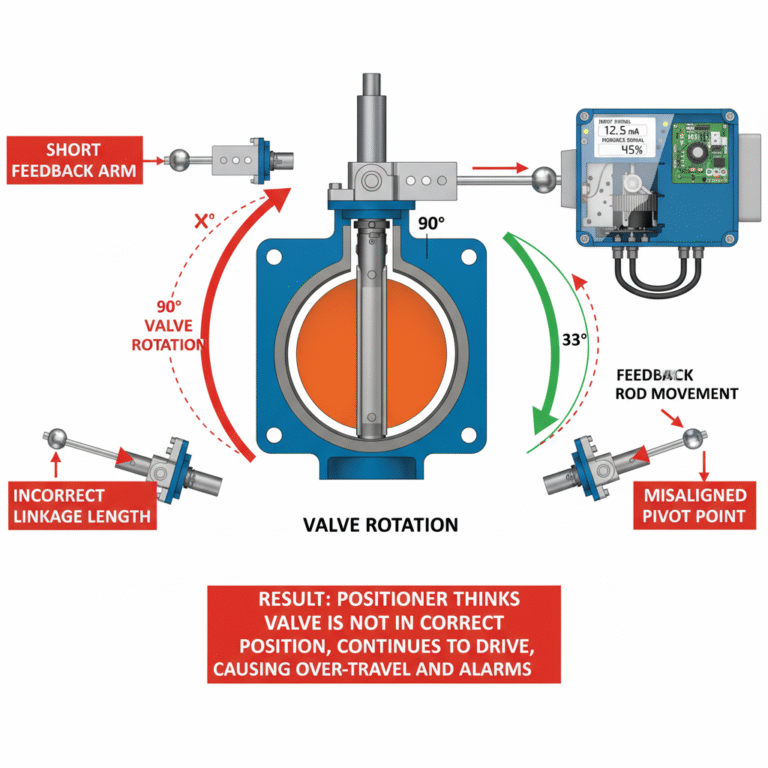
The mismatch problem often arises from the use of non-matching connection parts, such as feedback arms, linkages, or pivot points, which are critical for maintaining the correct ratio between the valve’s movement and the feedback rod’s movement.
When the connection components aren’t designed properly, several issues can occur:
Short feedback arms: The valve might rotate 90°, but the short feedback arm can only move the feedback rod by a smaller angle (e.g., 33°).
Incorrect linkage length: This can cause the feedback rod’s movement to either compress or expand, disturbing the intended ratio.
Misaligned pivot points: This further exacerbates the movement error, potentially causing feedback fluctuations.
In such cases, if the positioner is set to 90°, it will continuously receive incorrect feedback from the position rod and fail to control the valve accurately.
Conclusion: Why the 90° Setting is Incorrect
The core issue is not the “rotary stroke” of the butterfly valve itself but the mismatch between the valve’s stroke and the positioner’s feedback stroke. To achieve precise control, the positioner’s settings should be based on the feedback rod’s actual movement (33° in this case), not the valve’s 90° stroke. Therefore, even though the valve has a 90° angle of rotation, if the feedback rod only moves 33°, the positioner must be calibrated to this 33° range (or use a corresponding linear stroke setting) to ensure accurate control.
This underscores the importance of matching the valve with a suitable positioner and connecting components to maintain precise control in automated systems.