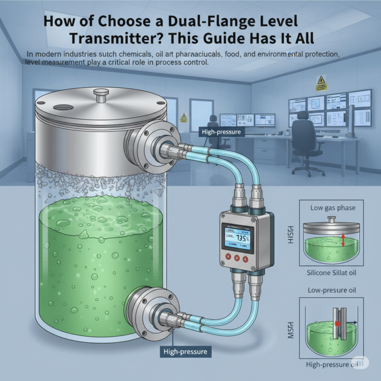
In modern industries such as chemicals, oil, pharmaceuticals, food, and environmental protection, level measurement plays a critical role in process control. For special media environments that are corrosive, prone to crystallization, high-viscosity, or prone to solidification, traditional differential pressure transmitters with capillary tubes often experience blockages, corrosion, or signal drift. In these cases, dual-flange level transmitters (Remote Seal Differential Pressure Transmitters) are an ideal solution, thanks to their sealed design, anti-clogging capabilities, and high stability.
1. Key Advantages of Dual-Flange Level Transmitters
Compared to traditional differential pressure transmitters, the dual-flange structure uses a diaphragm, capillary tube, and filling liquid system to completely isolate the sensing element from the measured medium. This design offers the following significant advantages:
Excellent Corrosion Resistance: The diaphragm can be made of materials like Tantalum, Hastelloy, 316L stainless steel, or Monel.
Anti-Clogging: The absence of capillary tubes makes it ideal for media containing solid particles or high-viscosity substances.
Wide Temperature Range: The filling liquid (typically silicone oil) maintains stability across a broad temperature range, making it suitable for high- or low-temperature environments.
Low Maintenance: The sealed design prevents media contamination or scaling, reducing the need for regular maintenance.
High Precision and Strong Interference Resistance: The output signal is stable with good linearity, making it suitable for long-term online measurements.

2. Basic Working Principle
The dual-flange level transmitter connects to the high-pressure and low-pressure sides of a container. As the liquid level changes, the static pressure changes accordingly, which is transmitted through the capillary tube filled with silicone oil to the sensing diaphragm. The differential pressure sensed by the diaphragm is then converted into an electrical signal (4-20mA or digital signal), achieving a linear correlation between liquid level and output signal.
Basic formula:
ΔP = ρ1gh
Where:
ρ1: Density of the measured liquid (kg/m³)
g: Gravitational acceleration (9.80665 m/s²)
h: Liquid level height (m)
From this, we derive the relationship between liquid level change and output signal:
L = ρ1gH
Where H is the liquid level corresponding to the full range, and L is the full-scale differential pressure (Pa).
3. Typical Installation Methods and Calculation
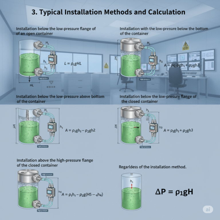
Based on the device structure, dual-flange level transmitters have the following installation options:
Installation below the low-pressure flange of an open container:
Measurement range:
L = ρ1gHLZero-point shift:
A = ρ1gh1Output range:
ΔP1 = A, ΔP2 = A + ρ1gHApplicable for: Open tanks or containers at atmospheric pressure.
Installation with the low-pressure flange below the bottom flange of the container:
In this case, the capillary tube filling static pressure must be considered:
A = ρ1gh1 + ρ2gh2
Output range: ΔP1 = A, ΔP2 = A + ρ1gH
Differential pressure range remains: ρ1gH.Installation with the low-pressure flange above the bottom of the container:
When the low-pressure side flange is positioned above the bottom of the container, compensation is required for negative filling pressure.
A = ρ1gh1 – ρ2gh2
Output range: ΔP1 = A, ΔP2 = A + ρ1gH
Zero-point shift will be negative and requires adjustment during commissioning.Installation below the low-pressure flange of a closed container:
High-pressure side connects to the bottom of the liquid, and the low-pressure side connects to the upper gas phase:
A = ρ1gh1 – ρ2gh3
Output range: ΔP1 = A, ΔP2 = A + ρ1gH
Installation above the high-pressure flange of a closed container:
When the transmitter is positioned above the upper flange, additional static pressure from the filling liquid must be considered:
A = ρ1gh1 – ρ2g(h5 – h4)
Output range: ΔP1 = A, ΔP2 = A + ρ1gH
Regardless of the installation method, the effective differential pressure range is always:
ΔP = ρ1gH

4. Calculation Verification Method
To ensure measurement accuracy, “calculation verification” should be completed before installation:
Parameters to determine: ρ1, ρ2, H, h1, h2, h3, etc.
Calculation:
L = ρ1gH
A = ρ1gh1 ± ρ2gh2 (depending on installation method)
ΔP1 = A, ΔP2 = A + ρ1gHVerification Steps:
Ensure the high and low-pressure flanges are at the same horizontal level.
Simulate static pressure difference and verify the linear output within the 4–20mA range.
Field check: Confirm that the transmitter’s output corresponds accurately to the liquid level.
5. Key Considerations for Selection and Configuration
| Item | Description | Recommended Configuration |
|---|---|---|
| Measured Media | Corrosiveness, viscosity, temperature | Tantalum, Hastelloy, 316L diaphragm |
| Installation Type | Open/closed container | Clarify positive/negative migration direction |
| Operating Temperature | -40°C to 300°C | Select high-temperature silicone oil filling |
| Environmental Conditions | Sun exposure, vibration, humidity | Use protective or encased structures |
| Output Signal | 4-20mA, HART, Modbus | Ensure compatibility with control systems |
6. Limitations of Dual-Flange Level Transmitters
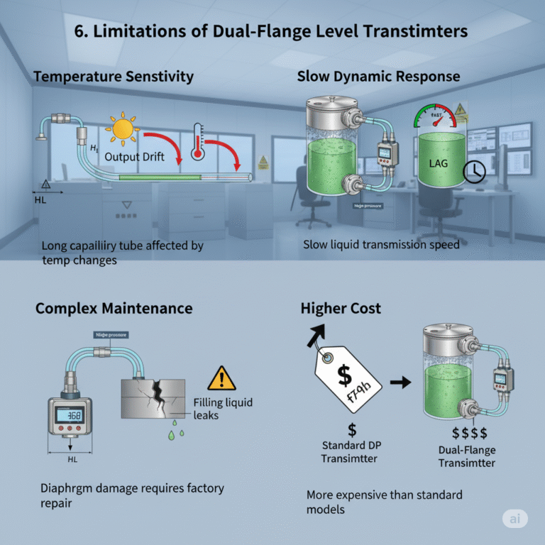
Despite their adaptability, dual-flange level transmitters have the following limitations:
Temperature Sensitivity:
The long capillary tube can be affected by temperature changes, causing expansion of the filling liquid and resulting in output drift.
Recommendation: Use temperature-compensated models or shorten the capillary tube length, and avoid direct sunlight exposure.Slow Dynamic Response:
The liquid transmission speed is slow, making it unsuitable for applications with rapid level changes.Height Limitations:
Long capillary tubes lead to lag and non-linear errors; ensure isothermal installation to minimize these effects.Complex Maintenance:
If the diaphragm is damaged or the filling liquid leaks, factory repairs are required. Regular sealing checks are recommended.Higher Cost:
Although more expensive than standard differential pressure transmitters, dual-flange models are more stable and reliable for long-term operation.

7. Common Faults and Maintenance Solutions
| Fault Phenomenon | Possible Cause | Solution |
|---|---|---|
| Signal Fluctuation | Uneven heating of capillary tube, environmental vibration | Strengthen supports, avoid heat sources |
| Large Zero Drift | Filling liquid expansion or leakage | Check joints, recalibrate, or replace filling liquid |
| No Output Signal | Diaphragm failure, wiring issues | Replace diaphragm assembly or check wiring |
| High-Level Reading | Incorrect migration direction | Correct migration settings on the transmitter |
| Low-Level Reading | Incorrect density setting | Reconfigure medium density compensation |
8. Engineering Application Examples
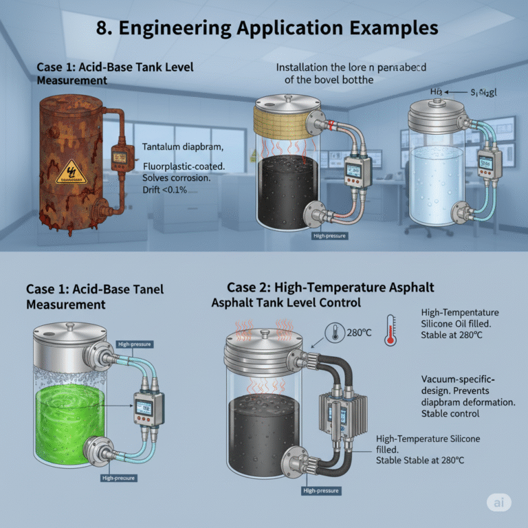
Case 1: Acid-Base Tank Level Measurement
Using a Tantalum diaphragm and fluoroplastic dual-flange level transmitter, long-term drift is kept below 0.1%, solving corrosion issues commonly associated with capillary tubes.Case 2: High-Temperature Asphalt Tank Level Control
A high-temperature silicone oil-filled transmitter maintains stable output even at temperatures up to 280°C.Case 3: Vacuum Reactor Level Monitoring
A vacuum-specific dual-flange transmitter, with special sealing design, prevents diaphragm deformation due to negative pressure, ensuring stable level control.

9. Conclusion
Dual-flange level transmitters offer excellent corrosion resistance, anti-clogging, and reliable sealing, making them ideal for complex level measurement applications. However, engineers and application personnel must be aware of their temperature sensitivity, response delay, and maintenance requirements. Strict control during the design, selection, installation, and calibration phases will ensure the long-term stable operation of these devices, safeguarding process safety and measurement accuracy.
