The integration of flow meters and differential pressure (DP) transmitters is based on the principle of differential pressure measurement. The DP transmitter converts the small differential pressure signals generated by the flow element into standard electrical signals, enabling accurate flow measurement and remote transmission. This creates a symbiotic relationship between “flow measurement” and “signal conversion.”
1. Core Principle: Differential Pressure Flow Measurement
According to Bernoulli’s equation, when a fluid flows through a “throttling element” (e.g., orifice plate, venturi tube) in a pipe, the flow area decreases, causing the flow velocity to increase and the static pressure to drop. This generates a fixed “differential pressure” across the element.
The differential pressure is proportional to the flow rate (either volumetric or mass flow rate), and the DP transmitter captures and converts this pressure signal. The secondary instrument (e.g., PLC, DCS) then calculates the actual flow rate based on a formula.
2. Key Components and Functions
The integration of flow meters and DP transmitters requires four key components to work in unison:
Flow Element (Core Measurement Device): Installed in the pipeline, this is the source of the differential pressure. Common types include:
Orifice Plate: Simple structure, cost-effective, suitable for clean fluids (e.g., water, steam).
Venturi Tube: Low-pressure loss, high accuracy, suitable for fluids with impurities (e.g., wastewater, slurry).
Nozzle: Wear-resistant, suitable for high-speed, high-temperature fluids (e.g., superheated steam).
Pressure Tapping (Signal Transmission): Connects the flow element’s upstream and downstream pressure ports to the DP transmitter, transmitting the differential pressure signal (fluid pressure) physically.
Differential Pressure Transmitter (Signal Converter): Converts the differential pressure signal (usually small pressures like 0-10 kPa) into a standard electrical signal (e.g., 4-20 mA DC), offering the advantages of anti-interference and long-distance transmission.
Secondary Instrument/Control System (Data Processing Terminal): Receives the standard signal from the transmitter and calculates the flow rate using the “differential pressure-flow” formula (which requires fluid density, pipe diameter, and other parameters). This can be used to directly display flow rates, accumulate totals, or control processes like valve adjustments.
3. Installation and Connection Details
Correct installation is critical to the accuracy of flow measurements. Key considerations include:
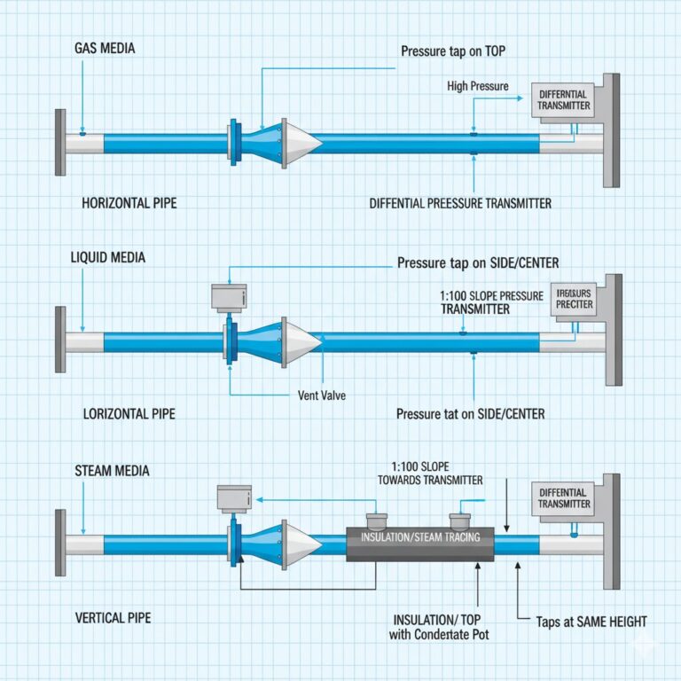
Pressure Tap Position:
Horizontal Pipes: For gas media, the tap should be positioned at the upper section (to avoid liquid accumulation). For liquid media, the tap should be placed near the centerline (to avoid gas accumulation). For steam, the tap should be at the upper section with a condensate pot.
Vertical Pipes: Pressure taps can be placed in any direction, but the upstream and downstream taps must be at the same elevation (to prevent extra differential pressure from height differences).
Pressure Tube Layout:
Length: Minimize the length (ideally less than 50 meters) to reduce signal delays and pressure losses.
Slope: For liquid media, the pressure tube should slope toward the transmitter (1:100 ratio). For gas media, it should slope toward the pressure tap to avoid liquid/gas accumulation.
Insulation/Heating: For steam or low-temperature fluids, the pressure tube should be insulated or heated (e.g., steam tracing) to prevent blockage caused by freezing or condensation.
Transmitter Installation:
Position: The transmitter should ideally be installed at the same height as the pressure tap. If adjustment is needed, the secondary instrument must compensate for the “liquid column difference” to maintain accuracy.
Vent and Drain: The transmitter should have vent and drain valves (for liquid and gas measurement respectively). After installation, purge the pressure tubes to ensure accurate readings.
4. Applications and Benefits
The integration of DP flow meters and transmitters is one of the most widely used flow measurement solutions in industry. It is particularly suitable for the following scenarios:
Media: Liquid (water, oil), gas (air, natural gas), and steam (saturated or superheated steam).
Operating Conditions: Medium to high pressure (up to 10 MPa) and medium to high temperatures (up to 400°C), typically in applications with moderate accuracy requirements (±0.5% to ±2.5%). This makes it ideal for industries like power generation, chemicals, and oil & gas.
Key Advantages:
Stable structure and low maintenance costs.
Suitable for harsh environments.
The standardized signal (4-20 mA) from the DP transmitter easily integrates with industrial control systems, enabling automated monitoring.