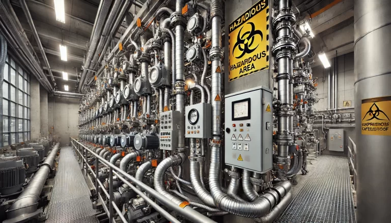
In hazardous environments such as petrochemical plants, battery material production, paint shops, and gas processing facilities, bringing ordinary electrical equipment safely into explosive areas is a major challenge.
One of the most reliable engineering solutions is Positive Pressure Explosion Protection (Ex p).
This article provides a comprehensive explanation of the Ex p principle, classification standards, key design components, calculation methods, installation and maintenance practices, and common pitfalls — helping engineers and maintenance teams fully understand and apply this safety system.
1. What Is Positive Pressure Explosion Protection (Ex p)?
Definition:
Ex p systems maintain a slight overpressure inside an enclosure or room by continuously supplying clean air or inert gas.
This positive pressure prevents the ingress of flammable gases or dusts, allowing non-explosion-proof electrical components to operate safely within the enclosure.
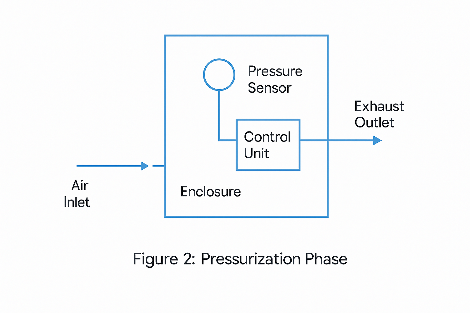
Core Mechanisms:
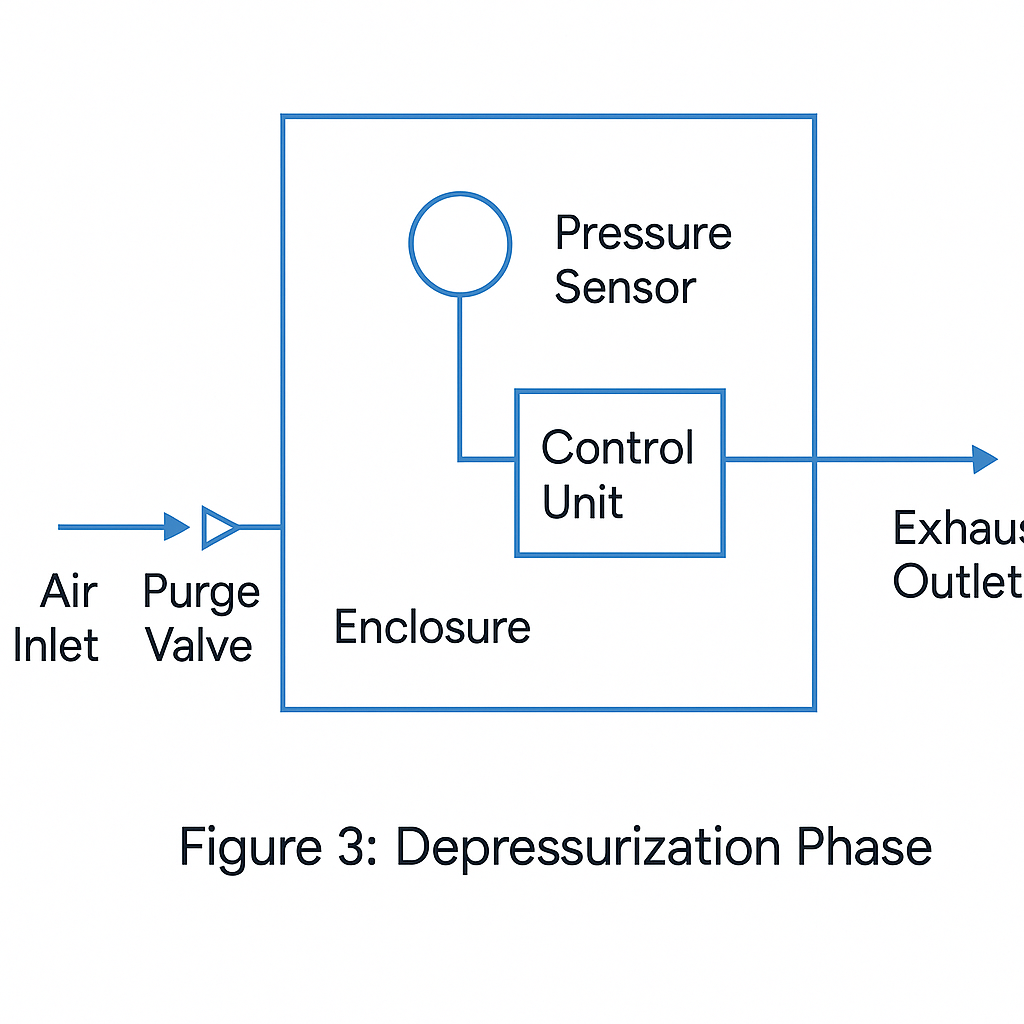
Purging: Before energizing, clean air is purged through the enclosure multiple times to remove any flammable substances.
Pressurization: During operation, a minimum pressure differential and make-up flow are maintained to resist leakage and infiltration.
Monitoring & Interlock: If pressure or airflow drops below safe limits, the system automatically triggers an alarm or power shutdown.
Typical reference values:
Purging air exchange: ≥5 times enclosure volume (IEC 60079-2)
Minimum operating overpressure: ≥50 Pa
2. Standards and Classification (IEC / EN 60079-2)
Ex p protection is standardized globally under IEC 60079-2, with regional equivalents such as NFPA 496 in North America and GB/T 3836 in China.
Types and Area Classifications:
| Type | Typical Area | EPL (Equipment Protection Level) | Characteristics |
|---|---|---|---|
| Ex px / py | Zone 1 | Gb | Continuous or monitored pressurization with air compensation |
| Ex pz | Zone 2 | Gc | Static pressurization allowed but requires pressure monitoring |
Additional References:
Ex p rooms: IEC 60079-13
Installation: IEC 60079-14
Inspection & maintenance: IEC 60079-17
North American reference: NFPA 496
In gas environments, control or analyzer cabinets usually adopt Ex px or Ex py types; dust environments require separate EPL marking for dust protection.
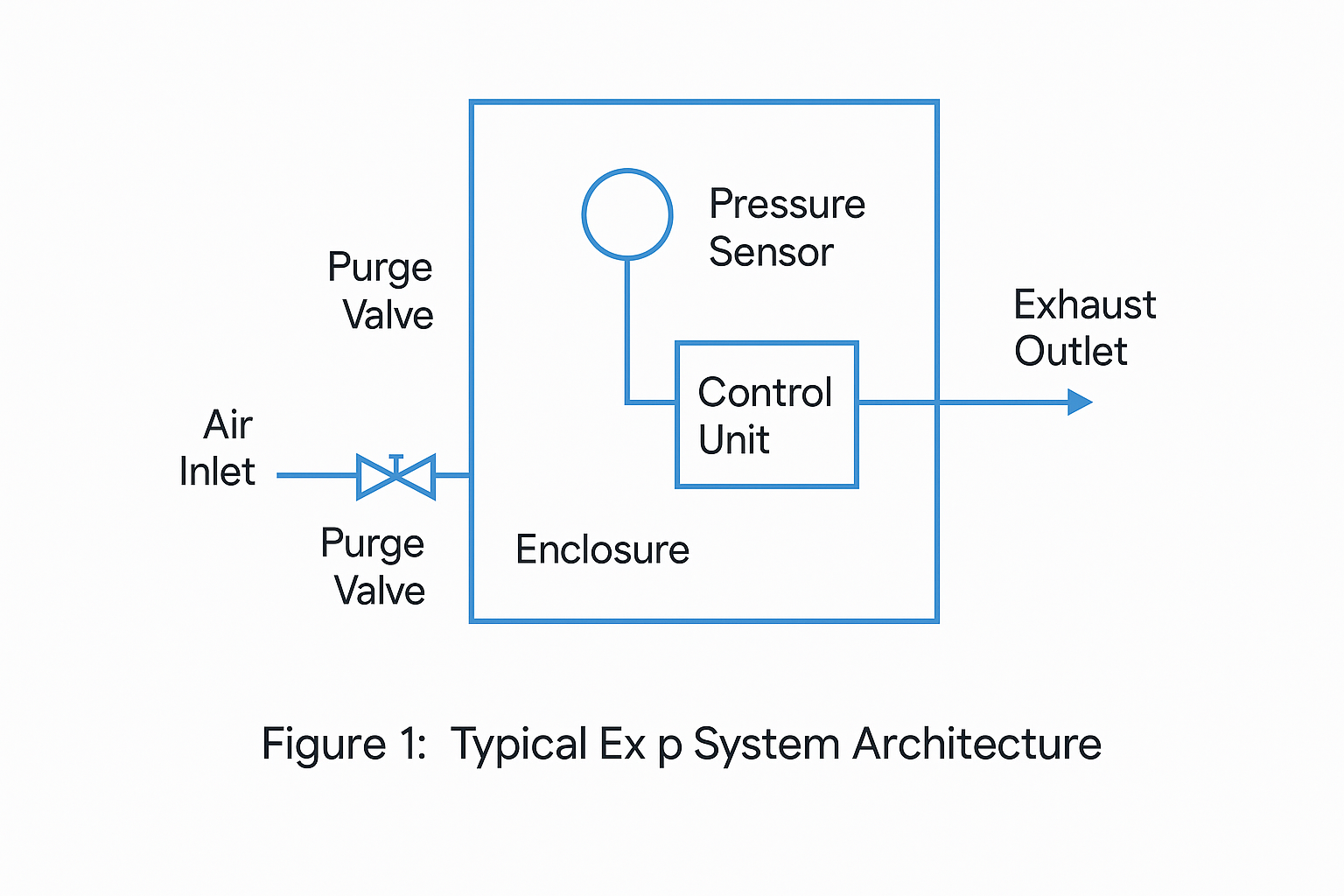
3. Key Components and System Architecture
A typical Ex p system consists of the following functional modules:
Pressurization Controller and Valve Group – integrates differential pressure sensors, flow meters, purge valves, and logic control.
Air or Gas Supply Unit – provides clean, dry compressed air or inert gas (e.g., nitrogen).
Enclosure and Sealing Design – ensures mechanical strength and low leakage rate.
Electrical Interlock System – triggers alarm/shutdown when underpressure or door-open conditions occur.
Display and Communication – local indicator plus remote DCS/ESD interface.
Engineering note:
Increasing supply flow alone cannot compensate for poor sealing. Leakage must be solved through design optimization, not brute-force airflow.
4. Selection and Design Calculations
To ensure a compliant and efficient Ex p system, the design should follow these key steps:
1. Define the Area and Medium
Hazardous zone classification (Zone 0/1/2 or Class/Division)
Gas or dust type, gas group, and temperature class (T-rating)
2. Verify Certification and Marking
Ex p type (px / py / pz)
Ambient temperature range and internal heat load
Compliance with IECEx / ATEX or GB/T 3836 standards
3. Purging and Volume Calculation
Purging volume = enclosure free volume × ≥5 times
Purging time = purging volume ÷ actual airflow rate
4. Pressurization and Leakage Compensation
Maintain ≥50 Pa pressure difference
Calculate minimum make-up air flow to balance leakage rate
Optimize sealing and venting paths
5. Control and Interlock Strategy
Underpressure / underflow alarm & shutdown
Door-open interlock and delayed purge restart
Integration with DCS or ESD for safety logic
6. Material and Anti-Corrosion
Select stainless steel or coated carbon steel for outdoor or coastal installations.
7. Thermal Management
Ensure internal temperature remains below T-class limit using fans, air ducts, or air conditioning.
5. Installation and Wiring Guidelines
Practical tips to avoid field mistakes:
Explosion Protection Continuity: External wiring must meet the same protection level (e.g., Ex e junction boxes or conduit seals).
Cable Sealing: Use barrier glands near cable entries to prevent gas ingress.
Grounding: Ensure reliable bonding and anti-static grounding for the enclosure and conduits.
Vent Placement: Exhaust air must avoid ignition sources or walkways.
Commissioning: Verify purge time, pressure differential, and interlock function; record all results for compliance documentation.
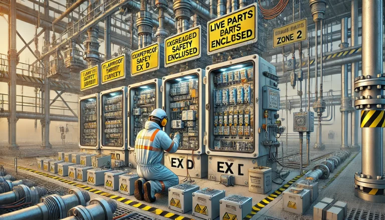
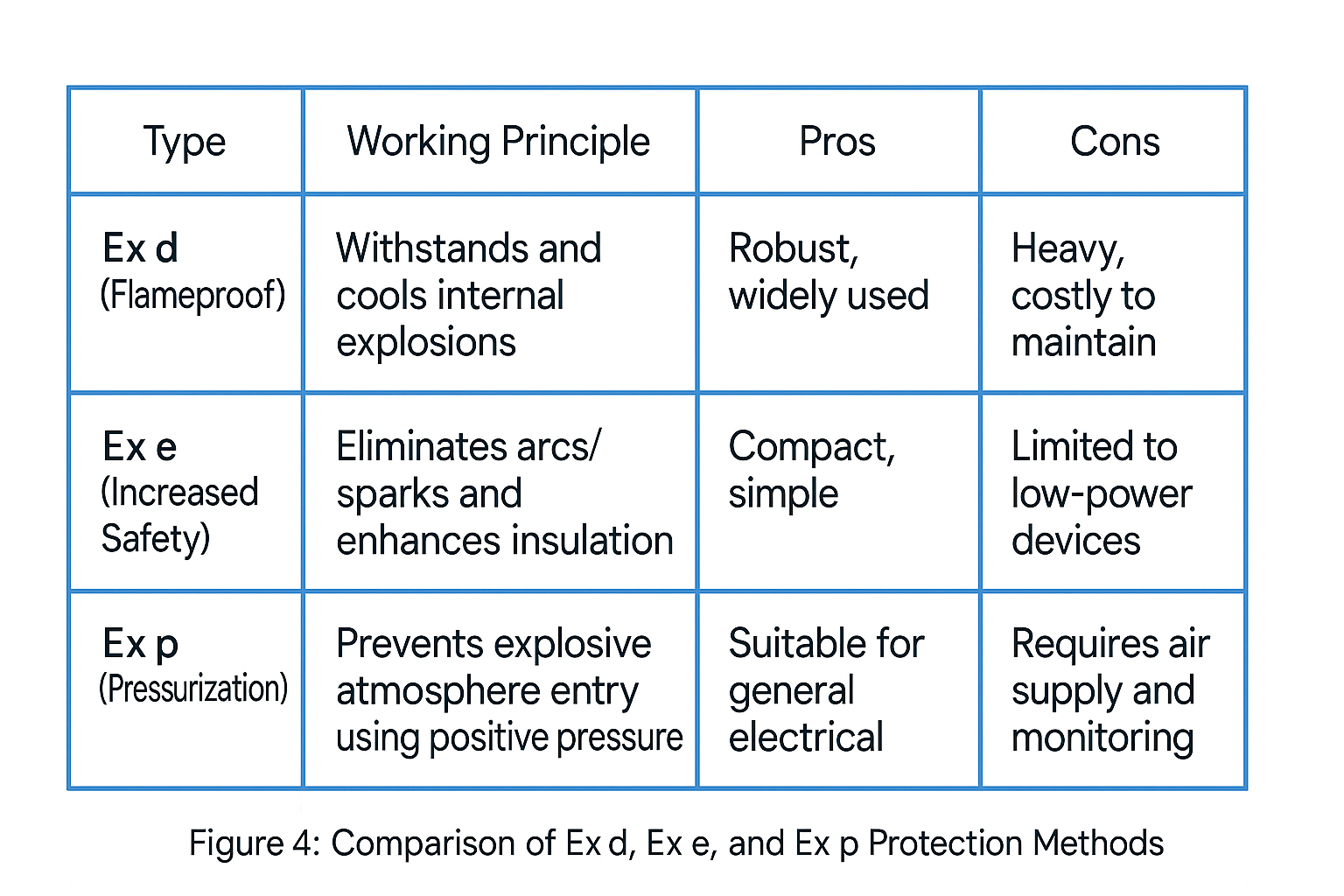
6. Comparison with Other Explosion Protection Methods
| Type | Working Principle | Pros | Cons |
|---|---|---|---|
| Ex d (Flameproof) | Withstands and cools internal explosions | Robust, widely used | Heavy, costly to maintain |
| Ex e (Increased Safety) | Eliminates arcs/sparks and enhances insulation | Compact, simple | Limited to low-power devices |
| Ex p (Pressurization) | Prevents explosive atmosphere entry using positive pressure | Suitable for general electrical assemblies | Requires air supply and monitoring |
Conclusion:
Ex p systems provide an optimal balance between safety and flexibility, especially for control panels, analyzers, and pressurized rooms containing non-Ex components.
7. Operation and Maintenance
To ensure long-term safety:
Routine Inspection: Check pressure differential, airflow, and alarm/shutdown functions.
Filter Replacement: Monitor filter pressure drop; replace as scheduled.
Record Keeping: Log purge times, fault resets, and maintenance actions.
Change Management: Recalculate purge volume and temperature rise if internal components are modified.
Safe Shutdown: System should safely de-energize on sensor or air supply failure.
8. Common Mistakes and Lessons Learned
“Blowing air only” without proper purge volume calculation
Ignoring external cable sealing or accessory protection
Relying on excessive air supply to offset leaks
Bypassing interlocks during continuous operation
Overheating due to unverified thermal design or T-class mismatch
Each of these issues has led to real-world Ex p failures — all preventable through proper engineering discipline.
9. Quick Reference for Key Engineering Values
| Parameter | Typical Value / Requirement | Reference |
|---|---|---|
| Purge cycles | ≥5 × enclosure volume | IEC 60079-2 |
| Operating overpressure | ≥50 Pa | IEC / GB standard |
| Enclosure strength | ≥1.5 × max operating pressure or ≥1200 Pa | IEC 60079-2 |
| Inert gas warning | Label “Asphyxiation hazard” if nitrogen used | Safety marking |
| Exhaust air | Vent to safe area or fit flame arrestor if venting to Zone 2 | Design rule |
10. Typical Application Scenarios
Pressurized Control Cabinets: Housing PLCs, drives, and HMIs in hazardous gas zones.
Analyzer Shelters / Pressurized Rooms: Hosting chromatographs and spectrometers, often with internal release sources.
Large Motors or Compressors: Enclosures filled with inert gas under Ex p certification for continuous operation in explosive areas.

Conclusion
The core value of Ex p explosion protection lies in keeping risk outside the enclosure — using measurable, monitorable, and interlocked engineering means to create an invisible safety barrier.
By mastering the five fundamentals — Purging, Pressurization, Monitoring, Thermal Control, and Sealing — engineers can ensure the long-term reliability and safety of Ex p systems.