RS485 is frequently misunderstood as a “communication protocol,” whereas in reality, it is a physical layer interface standard. This article explains the fundamentals of RS485, highlights common misconceptions, compares it with application protocols such as Modbus RTU, and provides practical engineering guidelines for installation, wiring, and troubleshooting.
1. What Exactly is RS485?
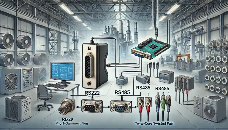
RS485 is not a protocol. It is a recommended standard (RS) defining the physical layer electrical characteristics for differential signaling. Its close relatives include RS232 (single-ended) and RS422 (differential, point-to-point). Among them, RS485 has become the most widely used in industrial automation due to:
Strong noise immunity and signal stability
Long-distance capability (up to 1200 m under ideal conditions)
Multi-drop support (one master with multiple slave devices)
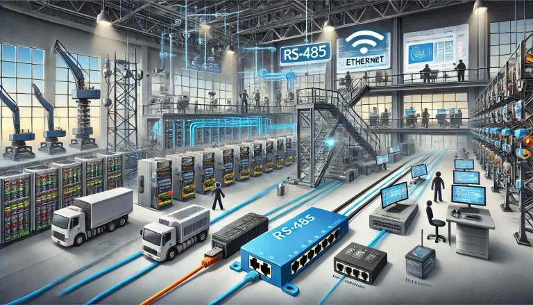
2. Wiring Considerations
The most reliable wiring method is the daisy chain (bus topology), where devices are connected in series along one cable.
RS485 can carry Modbus, but also many other protocols. They exist at different OSI layers.
Table 2 — RS485 vs. Modbus RTU in the OSI Model
OSI Layer
RS485 (Physical Layer Standard)
Modbus RTU (Application Protocol)
Application Layer
✗ Not defined
✓ Defines commands, function codes, and data structure
Presentation Layer
✗ Not applicable
✓ Encodes data fields into standardized frames
Session Layer
✗ Not applicable
✓ Defines master–slave interaction and request/response
Transport Layer
✗ Not applicable
✗ Relies on underlying serial link (no transport abstraction)
Network Layer
✗ Not defined
✗ Operates directly on serial line, no addressing beyond slave IDs
Data Link Layer
✗ Not defined
✓ Defines frame boundaries, error checking (CRC)
Physical Layer
✓ Defines differential signaling, wiring, voltage levels
✗ Relies on RS485 (or RS232, RS422, TCP/IP as carriers)
6. Communication Speed: Debunking the “Slow” Myth
Speed depends on:
Data size per frame
Baud rate and hardware conditions
Modbus RTU messages are compact and efficient. The limitation lies in serial communication speed, not the protocol itself. For most industrial applications, typical response times (tens of ms) are more than sufficient.
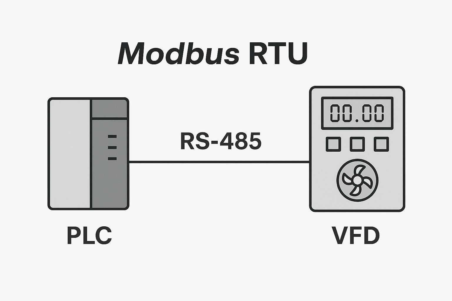
7. Master-Slave Architecture
The most common setup is one master with multiple slaves on RS485.
Pros: Simple wiring, low cost
Cons: Polling mechanism reduces efficiency, unsuitable for ultra-high-speed demands
This reflects a trade-off: cost-effectiveness vs. performance.
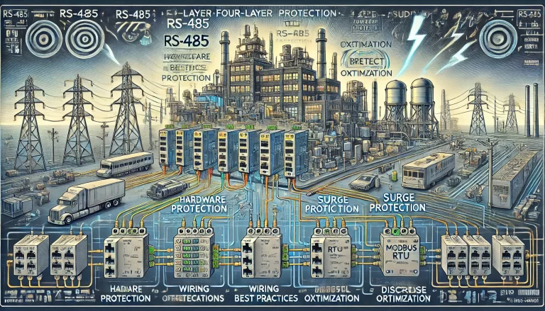
8. Summary
RS485 is a physical layer standard, not a protocol.
Use bus topology (daisy chain), avoid star connections.
Limit devices per bus; split large systems into multiple buses.
For long distances, use termination resistors or repeaters.
Modbus RTU often runs on RS485, but they are not interchangeable concepts.
Communication “slowness” is caused by serial hardware limits, not the Modbus protocol.
Ultimately, the key to successful RS485 system design is choosing the right topology, cable, and device distribution for the application scenario.