Differential pressure gauges (often used with differential pressure transmitters) are designed to measure the pressure difference between two process points. To ensure safe operation and measurement accuracy, strict operating rules must be followed when using the three-valve manifold. The primary objective is to protect the differential element (e.g., diaphragm capsule) from overpressure, pressure shock, or vacuum damage.
2. Structure and Function of the Three-Valve Manifold
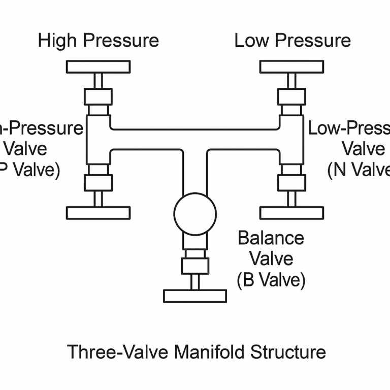
A standard three-valve manifold consists of three valves connected to the differential pressure gauge:
Valve Name
Connection
Main Function
High-Pressure Valve (P Valve)
Connects the process high-pressure side to the gauge’s high-pressure chamber
Controls high-pressure medium entry
Low-Pressure Valve (N Valve)
Connects the process low-pressure side to the gauge’s low-pressure chamber
Controls low-pressure medium entry
Balance Valve (B Valve)
Directly connects the high- and low-pressure chambers
Equalizes pressure on both sides; used for venting/draining
3. Operating Procedures
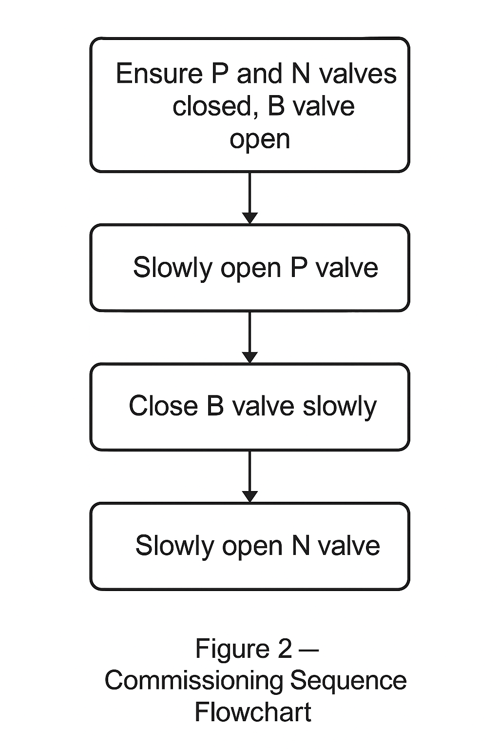
3.1 Commissioning (“Putting into Service”)
Principle: Equalize first, then pressurize Steps:
Initial Condition: Ensure P and N valves are fully closed; B valve fully open (both chambers at equal pressure).
Slowly Open P Valve: Open gradually (¼ turn each time). Observe gauge reading. Keep B valve open so no differential pressure is applied.
Close B Valve Slowly: After the P valve is fully open and stable, close B valve carefully.
Slowly Open N Valve: Open gradually until fully open. The gauge now receives both high- and low-pressure inputs, differential measurement begins.
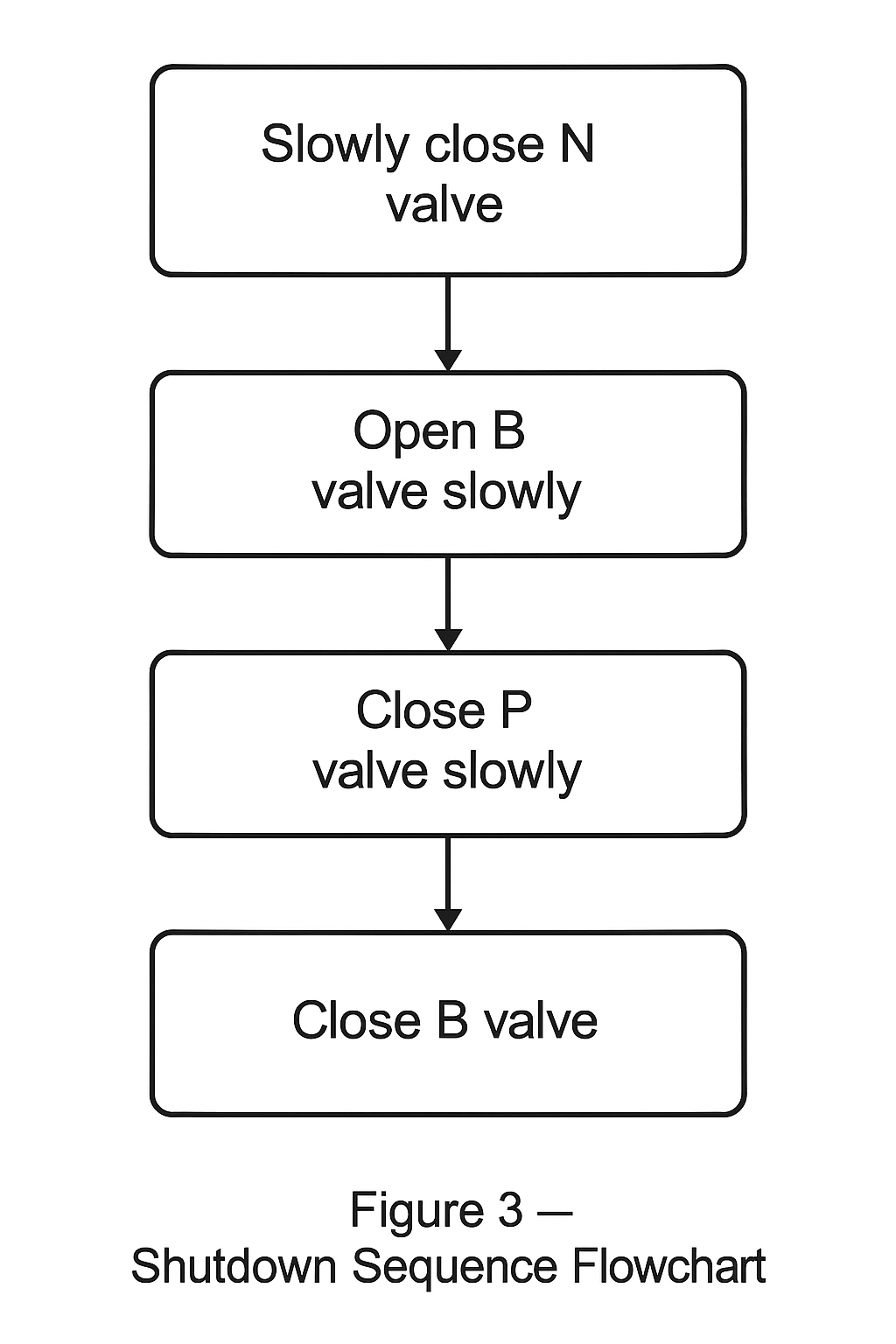
3.2 Shutdown (“Taking out of Service”)
Principle: Cut off pressure first, then equalize Steps:
Close P Valve Slowly – Cut off the high-pressure side.
Close N Valve Slowly – Cut off the low-pressure side.
Open B Valve Slowly – Equalize both chambers, relieve trapped pressure to zero. Safe for removal or maintenance.
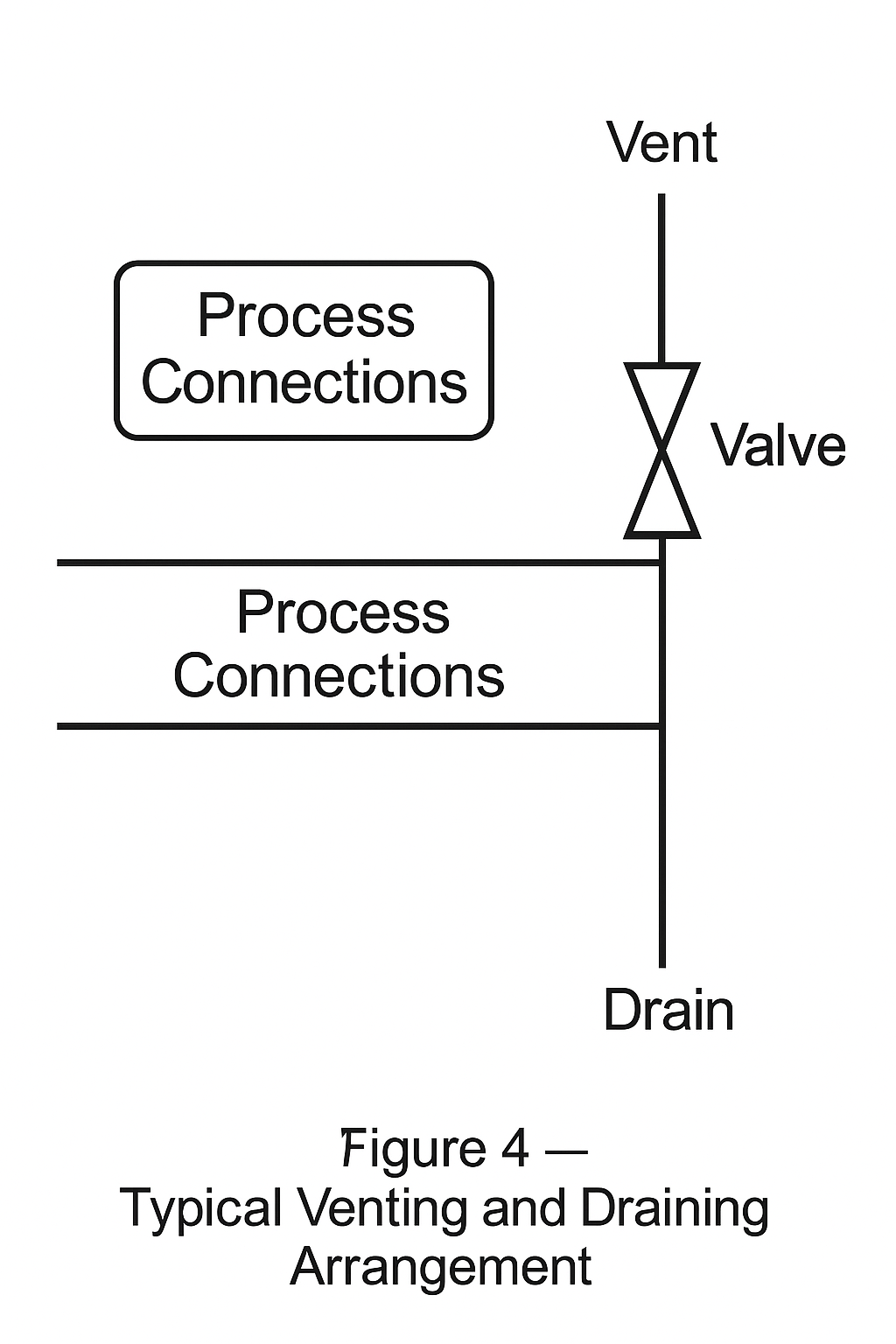
3.3 Venting and Draining
Venting (liquid service with trapped air): Keep P & N valves open, B closed. Use vent valves to discharge air until liquid flows continuously.
Draining (gas service with condensate): Close P & N valves, open B valve, drain accumulated liquid via drain ports.
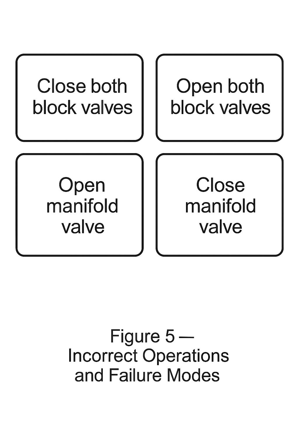
4. Prohibited Operations
Opening P or N without B open → Causes unilateral overpressure/vacuum, damaging diaphragm.
Opening B while P & N are open → Sudden equalization, pressure shock.
Rapid valve operation → Water hammer / gas hammer risk.
Leaving B valve open permanently → No valid measurement; contamination or moisture ingress possible.
5. Special Considerations
High Pressure (>10 MPa): Use stainless steel manifold; extend opening/closing intervals (3–5 s each step).
Corrosive Media (acid/alkali): Use corrosion-resistant materials (Hastelloy, PTFE lining). Clean surfaces after use.
Extreme Temperature (<–40 °C or >200 °C): Prevent freezing or burns; avoid forcing valves due to expansion/contraction.
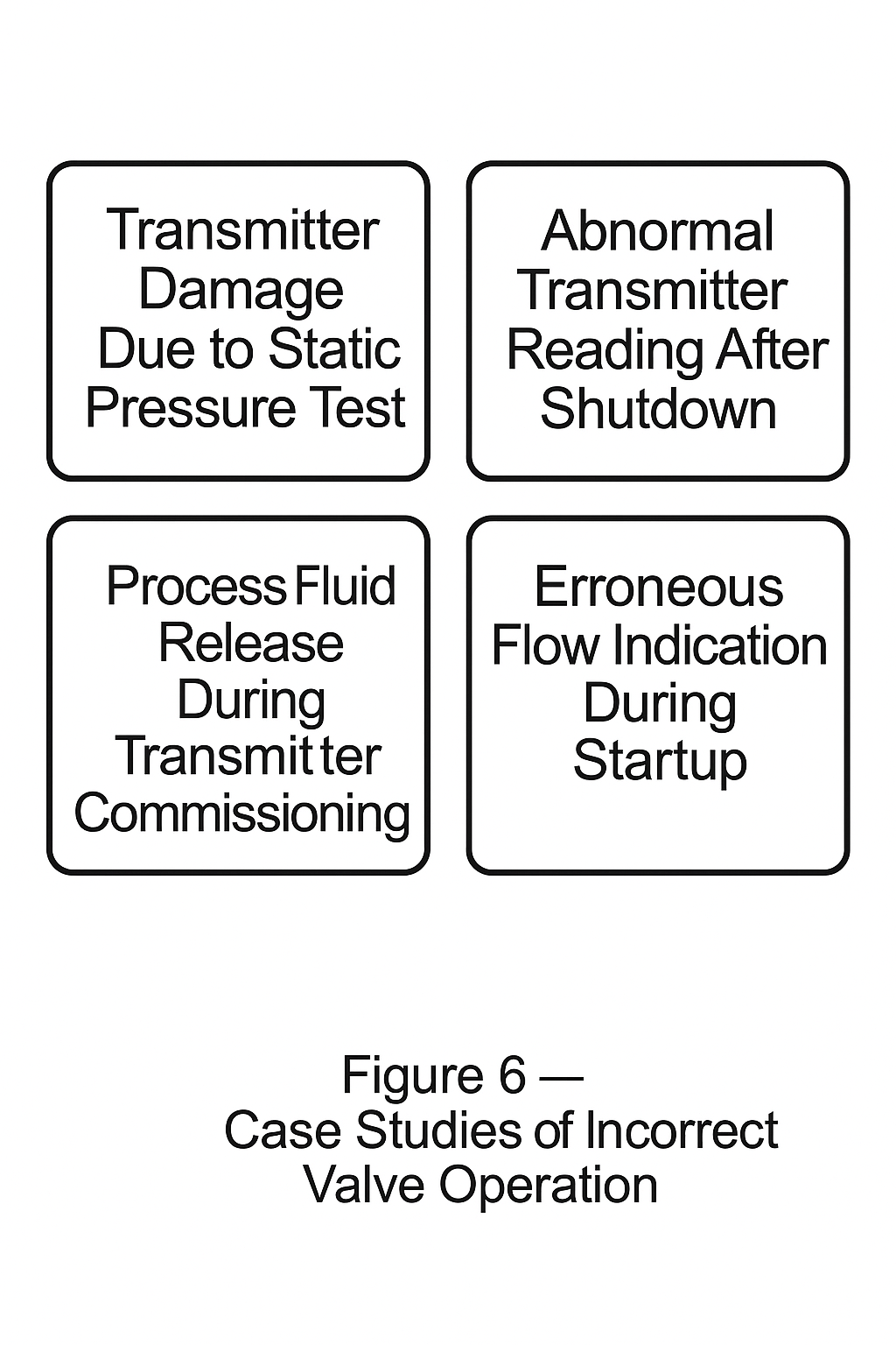
6. Failure Cases from Incorrect Operation
Diaphragm Damage: P valve opened before B valve → one-sided pressure overload.
Condensate Loss: All valves opened simultaneously → cold condensate blown out, false zero readings.
Frequent Blockage: Wrong shutdown order → manifold blockage increased by 300%.
7. Conclusion
Safe operation of differential pressure gauges with three-valve manifolds follows the principle: “Equalize first, then pressurize; depressurize first, then equalize.” Failure to comply may result in permanent instrument damage or unreliable readings. Always consult the instrument manufacturer’s manual and adapt the procedure to site-specific conditions.