The installation of instrument junction boxes must comply with relevant design and construction standards. The following guidelines summarize best practices based on HG/T 20512-2014 Instrument Piping and Wiring Design Code and related industry standards.
1. Location and Height
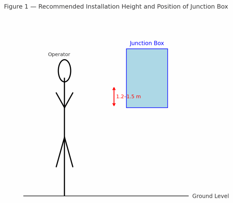
Height Requirement: The center of the junction box should be installed at a height of 1.2–1.5 m above the operating floor level, ensuring convenient access for wiring and maintenance.
Environmental Conditions: Select a location with sufficient lighting, good ventilation, no vibration, free of corrosive gases, and minimal electromagnetic interference. The installation must not obstruct operation, passage, or equipment maintenance.
Concentrated Arrangement: For areas with a high density of measuring points, junction boxes should be installed centrally to facilitate unified management and maintenance.
2. Mounting and Protection
Mounting Accuracy: Junction boxes must be securely mounted. The vertical deviation shall not exceed 3 mm (when height ≤1.2 m), and the horizontal deviation shall not exceed 3 mm.
Material Isolation: When different materials are used for junction box and support brackets, isolation pads (rubber or PTFE) shall be applied at contact surfaces to prevent galvanic corrosion.
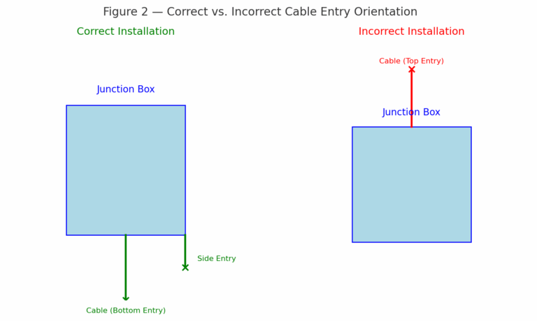
Sealing and Weatherproofing: Junction boxes shall provide effective sealing. Cable entries should preferably face downward to prevent ingress of rainwater and dust.
3. Cable Routing and Connections
Cable Entry Direction: For outdoor junction boxes, cables should enter from the bottom (bottom-in/bottom-out) or side-in/bottom-out. Top-entry wiring should be avoided.
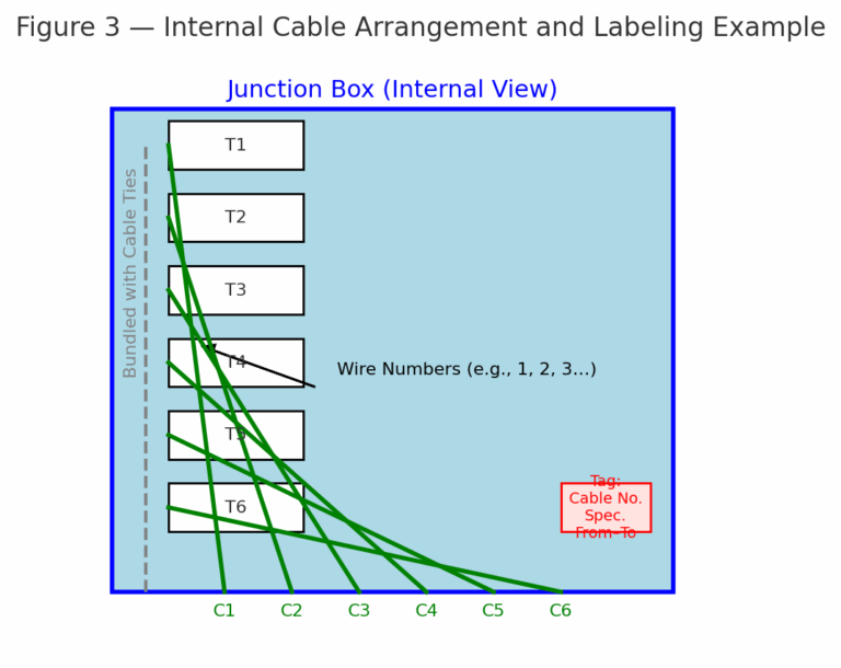
Cable Slack: Adequate slack shall be reserved inside the junction box. Excess cables should be coiled into loops of 200–300 mm in diameter and secured with cable ties.
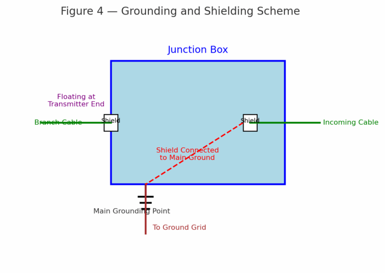
Shield Grounding: Cable shields must be grounded in accordance with design requirements. The main cable shield shall be grounded inside the junction box, while branch cable shields shall remain floating at the transmitter end.
4. Grounding and Identification
Grounding Requirements: The junction box enclosure and the main shield conductor shall be reliably grounded. Ground resistance shall meet design specifications.
Identification Standards: Junction boxes must be clearly numbered both inside and outside. Internal wiring shall be labeled with wire numbers. Hanging tags should indicate cable number, specification, origin, and destination.
5. Internal Wiring and Arrangement
Wiring Orderliness: Internal cables must be neatly bundled with cable ties, routed along the box wall, and arranged in orderly rows at terminal blocks.
Shield Protection: Shield wires shall be insulated using heat-shrink tubing to prevent short circuits or poor grounding.
6. Standards and References
These guidelines are based on:
HG/T 20512-2014 — Instrument Piping and Wiring Design Code
GB/T 4208 — Degrees of Protection (IP Code)
GB 50057 — Design Code for Lightning Protection of Buildings