Failure Type: Abnormal indication in control room (intermittent alarms, unstable signal).
Application: Installed below a pulverized coal bag filter, used for low-level detection of coal powder mixed with inert gas.
Objective: To detect coal powder accumulation and trigger timely discharge to storage silo, preventing excessive build-up.
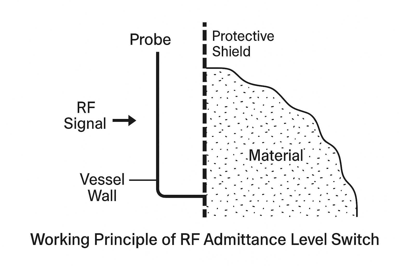
2. Working Principle
The RF admittance level switch operates on radio frequency capacitance technology:
A radio frequency is applied to the probe.
The surrounding environment causes a shift in dielectric constant, altering total impedance.
The instrument continuously analyzes this change to determine the presence of material.
Key Advantage: Unlike standard capacitance probes, RF admittance switches use a protective shield circuit to minimize errors caused by material build-up.
3. Instrument Features
High Versatility – Applicable for conductive and non-conductive media (liquids, slurries, powders, fly ash).
Anti-Coating Capability – Special circuitry reduces false signals caused by material adhesion.
Modular Design – Controller can be detached without disturbing process connections.
Wide Temperature Range – -184°C to +280°C (higher ranges available with ceramic insulation).
Flexible Output – SPDT relay signal output with LED status indicator and adjustable delay (0–30 seconds).
4. Operating Conditions
Medium: Pulverized coal + inert gas
Installation Location: Under the bag filter, low-level detection point
Normal Status: Alarm ON in standby, alarm cleared when material detected
5. Failure Phenomenon
The control room reported:
Signal fluctuation and intermittent alarms
Alarm sometimes cleared, sometimes re-triggered without clear process change
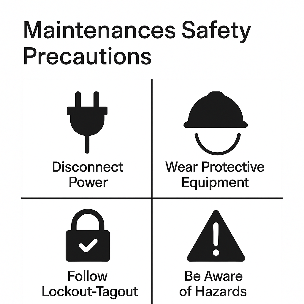
6. Safety Precautions Before Maintenance
Communicate with process operator and confirm failure symptoms.
Issue work permit, deactivate interlocks, conduct risk assessment.
Hand over equipment safely for maintenance.
Wear protective clothing and PPE, carry a multi-gas detector to monitor CO₂.
Always conduct maintenance with two personnel (one in action, one supervising).
Confirm safe escape route before entering restricted areas.
Ensure correct use of tools to avoid injury or damage.
7. Root Cause Analysis
Potential causes considered:
Loose or corroded power supply connection; voltage mismatch or overload.
Signal transmission faults: loose, broken, or disconnected cables.
Incorrect sensitivity or delay settings, leading to relay chatter.
Probe damage caused by collision or corrosion at high temperature.
Circuit board malfunction, spark protection circuit failure, or component damage.
Material build-up (coal dust, fly ash) on the probe surface, causing false alarms.
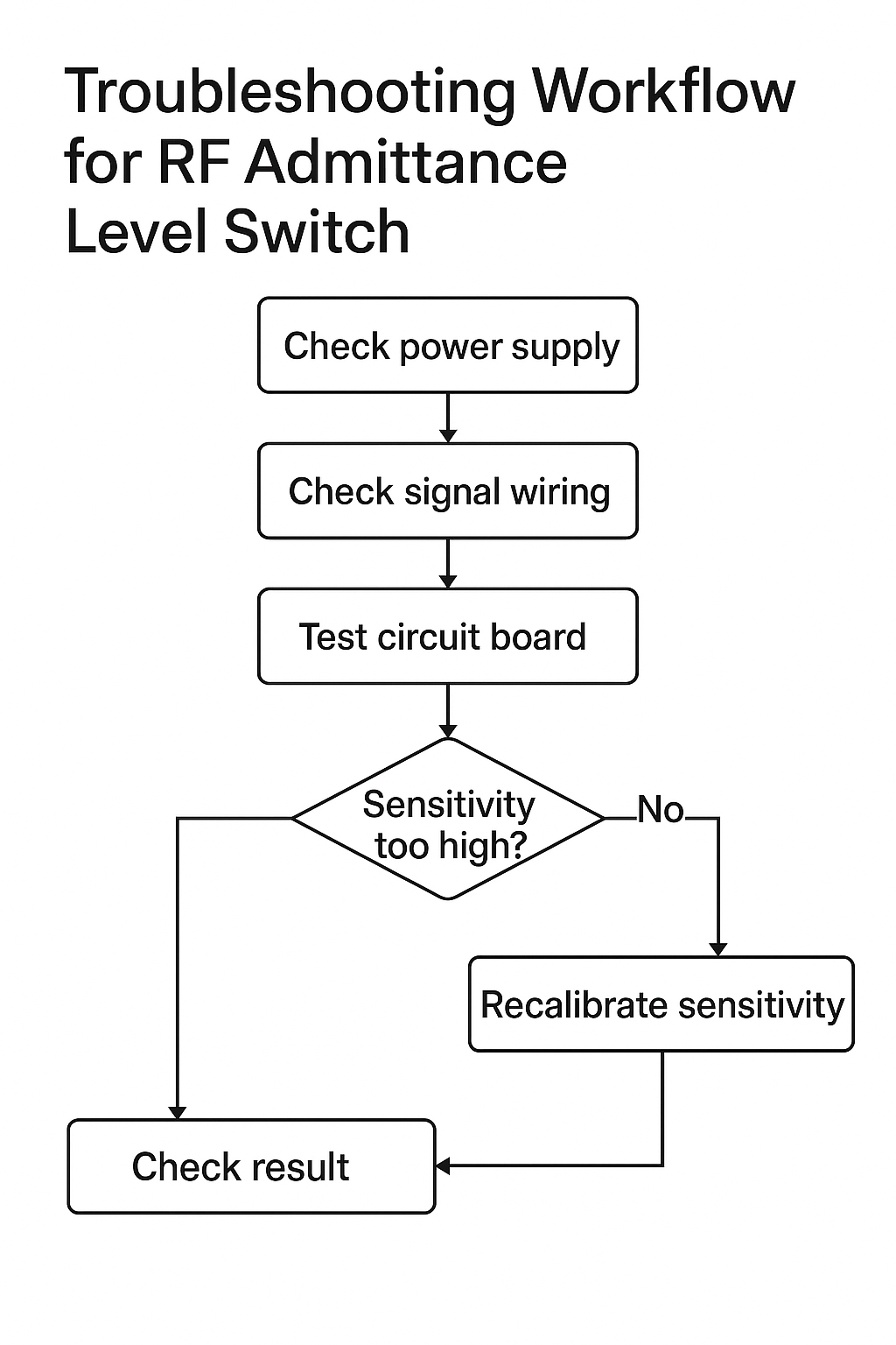
8. Troubleshooting & Corrective Actions
Measured power voltage with multimeter; checked terminals for looseness/corrosion.
Inspected signal wiring for continuity and integrity.
Adjusted sensitivity and delay settings (coarse “C” first until red LED, then fine “F”).
Replaced probe with identical model to confirm compatibility with process temperature.
Verified circuit board functionality, replaced if necessary.
Cleaned probe surface and re-checked installation method.
Result: Sensitivity was set too high. After recalibration, the control room reported stable and correct indication.
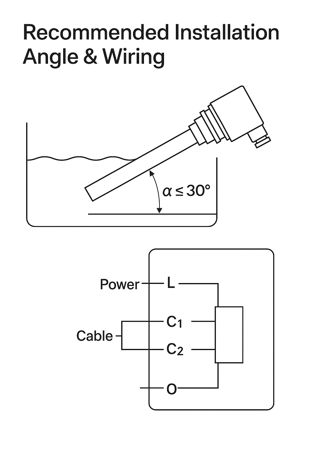
9. Installation Guidelines
Install at a 20° downward angle from horizontal to reduce impact and improve sensitivity.
Insulated portion should extend 50 mm beyond expected build-up layer on vessel wall.
Cable entry downward to prevent water ingress in outdoor environments.
Consider angle of repose if material piles unevenly.
Verify power voltage matches nameplate, connect cables according to terminal diagram, and close junction box tightly.
Ensure control circuit load does not exceed relay rating.
10. Sensitivity Adjustment
Coarse and fine knobs set fully clockwise before adjustment.
Delay set to zero initially.
Rotate coarse knob counter-clockwise until LED just turns red.
Fine knob adjusted counter-clockwise by two marks (higher sensitivity at smaller angle).
Avoid excessive force on knobs.
High-Level Alarm (H): Triggered when material present, COM/NO closed, COM/NC open. Low-Level Alarm (L): Triggered when no material present, COM/NO closed, COM/NC open. (Default factory setting: Low-Level alarm mode).
Delay Function: Adjustable up to 30 seconds to reduce false alarms caused by agitation.
11. Routine Maintenance
Probe Cleaning – Regularly remove deposits according to material type.
Wiring Inspection – Check cable integrity and junction box sealing.
Periodic Calibration – Ensure long-term accuracy under changing conditions.
Installation Protection – Avoid areas prone to vibration, corrosion, or mechanical impact.
Spare Parts Preparedness – Keep replacement probes and boards on hand for quick swap.
12. Lessons Learned
Excessive sensitivity can result in false alarms, especially in dusty media.
Proper calibration and delay setting are critical for reliable operation.
Preventive cleaning and inspection significantly reduce nuisance failures.
This case reinforces the importance of combining electrical checks with process condition review during troubleshooting.