1. Introduction
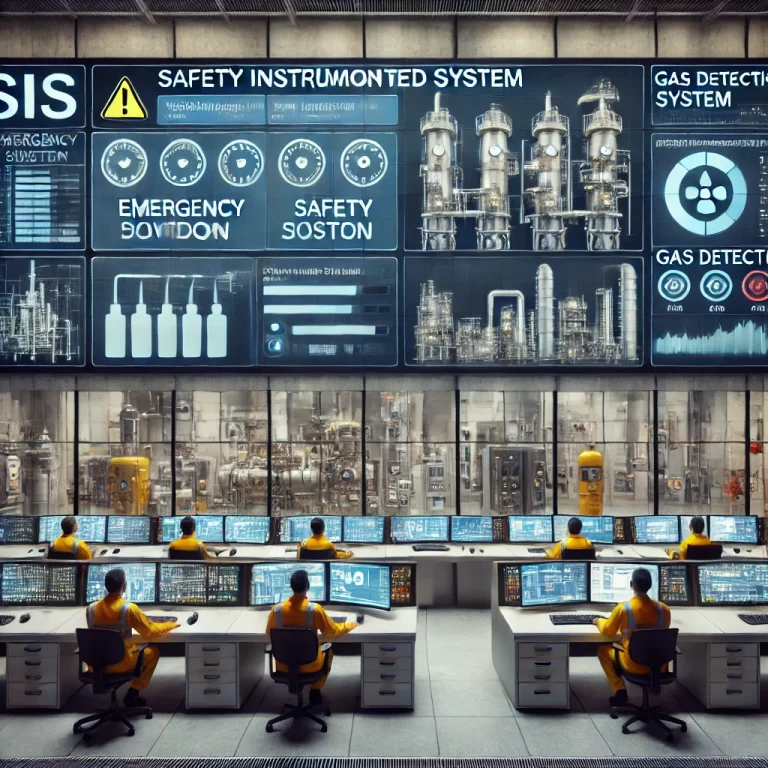
The purpose of this document is to establish standardized requirements for the operation, inspection, maintenance, and overhaul of the Safety Instrumented System (SIS).
The SIS is defined as an instrumentation system used to execute one or more Safety Instrumented Functions (SIF). It consists of sensors (e.g., switches, transmitters), logic solvers (controllers), and final control elements (e.g., solenoid valves, actuators).
2. Scope and Frequency
Scope: This procedure applies to all SIS subsystems within the designated plant or workshop.
Routine Operation Check: Performed daily during normal patrol inspection.
Shutdown Overhaul: Conducted during major plant turnarounds, with an interval not exceeding five (5) years.
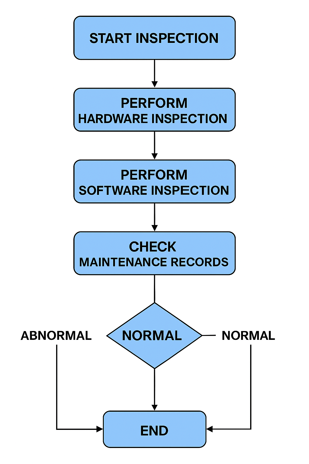
3. Routine Operation Checks
3.1 Hardware Inspection
Inspect controller cabinets, modules, operator stations, and communication networks.
Verify main and redundant equipment are operating normally.
Check UPS voltage, DC power supply, and redundant sources.
Inspect cooling fans, cabinet cleanliness, and engineer room temperature/humidity.
Review daily maintenance defect records and list unresolved issues.
3.2 Software Inspection
Perform complete backup of SIS software and data (including volatile memory).
Verify correct operation of monitoring and configuration software.
Confirm SOE (Sequence of Events) recording is enabled and functioning.
Check historical trends, fault log records, and system self-diagnostics.
Verify alarm system for redundancy loss, abnormal switching, data overflow, or bus failures.
3.3 Maintenance During Operation
Diagnose and correct system fault alarms, replacing modules if redundancy allows.
Ensure operator/engineer stations are functioning properly.
Configuration changes must be approved by the process department; no online editing during operation.
Isolate instruments before maintenance, confirm loop health before reintegration.
Maintain detailed Fault Record Ledger and Software Modification Register.
Prevent introduction of computer viruses (no unauthorized third-party software).
Change passwords periodically and ensure secure management.
4. Shutdown Overhaul Tasks
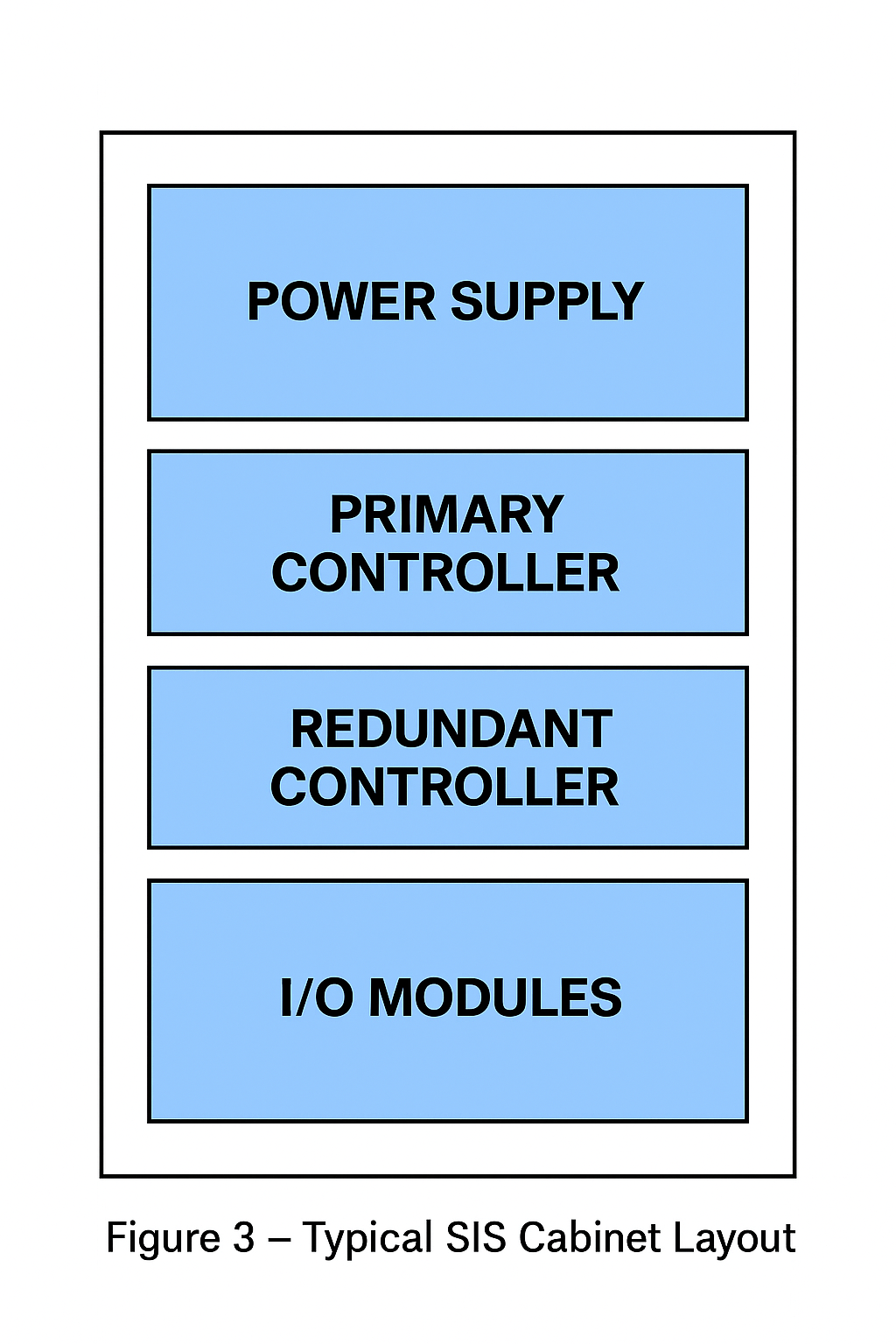
4.1 Cabinet and Module Maintenance
Perform dust removal and cleaning.
Replace depleted backup batteries.
Inspect modules for burns, cracks, or damaged pins; correct or replace as necessary.
Verify all connectors, shielded cables, and grounding are firm.
4.2 Operator and Engineer Stations
Clean internal/external components and cooling fans.
Verify power-up self-tests, status indicators, and normal OS/software startup.
Ensure display clarity, keyboard and mouse responsiveness, and correct user permissions.
4.3 Network and Interface Devices
Replace faulty cables or fiber optics, ensure proper routing and fastening.
Clean and inspect switches, repeaters, and converters; tighten connections.
Confirm redundant bus communication and diagnostic indicators are normal.
4.4 Power Supply Systems
Clean power modules and fans.
Confirm redundancy switching works correctly without system disturbance.
5. Inspection and Testing Procedures
5.1 Power-On Tests
Verify no abnormal sound, odor, or excessive temperature rise.
Confirm stable voltage outputs.
Check power redundancy by disconnecting one source.
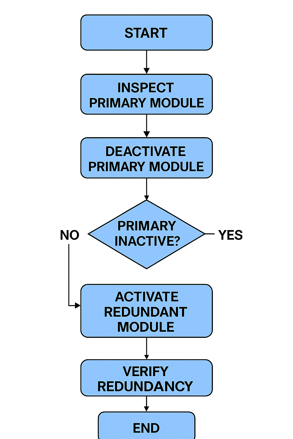
5.2 Redundancy Performance Tests
Operator Station Switching Test
Controller/Module Switching Test
Communication Bus Redundancy Test
Power Supply Redundancy Test
During tests, the system must switch seamlessly to standby devices without data loss, crash, or unexpected shutdown.
5.3 Channel Function Tests
Analog Input (AI): Input 0%, 25%, 50%, 75%, 100% signal and verify display values.
Analog Output (AO): Set output values in 0–100% range and confirm proper response of protective devices.
Digital Input (DI): Short/open contacts or apply/remove level signals and verify changes.
Digital Output (DO): Switch “ON/OFF” states and confirm field action.
5.4 System Configuration & Online Download Tests
Verify engineer/operator station permissions.
Perform logic changes, compilation, online download, and SOE verification.
Confirm monitoring graphics, alarm functions, and historical trends operate normally.
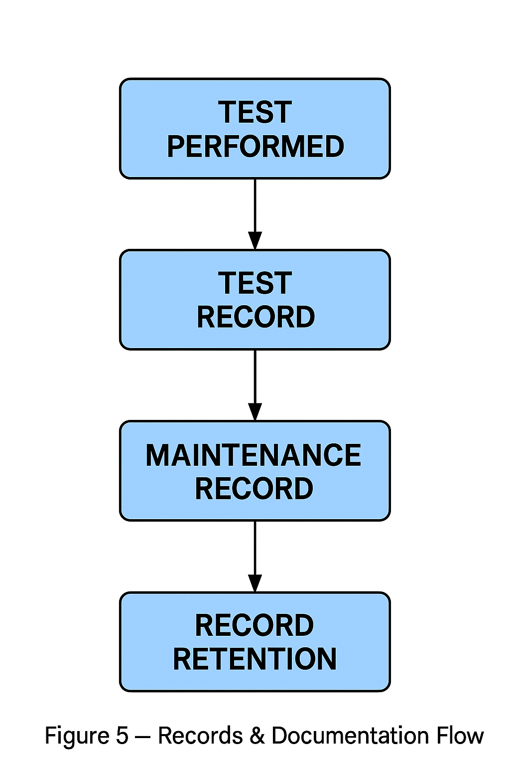
6. Records and Documentation
6.1 Daily Operation Checklist (Sample)
| Item | Inspection Content | Result (OK/NG) | Remarks |
|---|---|---|---|
| UPS Voltage | Verify stable supply | ||
| Cooling Fans | Rotation, no abnormal noise | ||
| SOE Recording | Enabled and running | ||
| Historical Trends | Normal data storage | ||
| Alarm Logs | Checked and reviewed |
6.2 Shutdown Overhaul Checklist (Sample)
| Item | Task | Completed (Yes/No) | Remarks |
|---|---|---|---|
| Cabinet Cleaning | Dust removal, anti-static | ||
| Backup Battery | Replaced if low | ||
| Network Cables | Inspected & secured | ||
| Redundant Bus | Tested & verified | ||
| Power Modules | Switching tested |
6.3 Records to Maintain
Fault Record Ledger
Software Modification Register
Periodic Inspection Reports
Overhaul Reports
System Test Certificates
7. Safety & Management Requirements
All maintenance work must comply with anti-static protection and lock-out/tag-out procedures.
Responsibilities:
Operators: Daily monitoring and reporting.
Instrument Technicians: Routine inspection and corrective maintenance.
System Engineers: Configuration management, backups, functional tests.
Reports and records must be archived for minimum five (5) years.
All tests and inspections must comply with IEC 61511 and local SIL validation requirements.