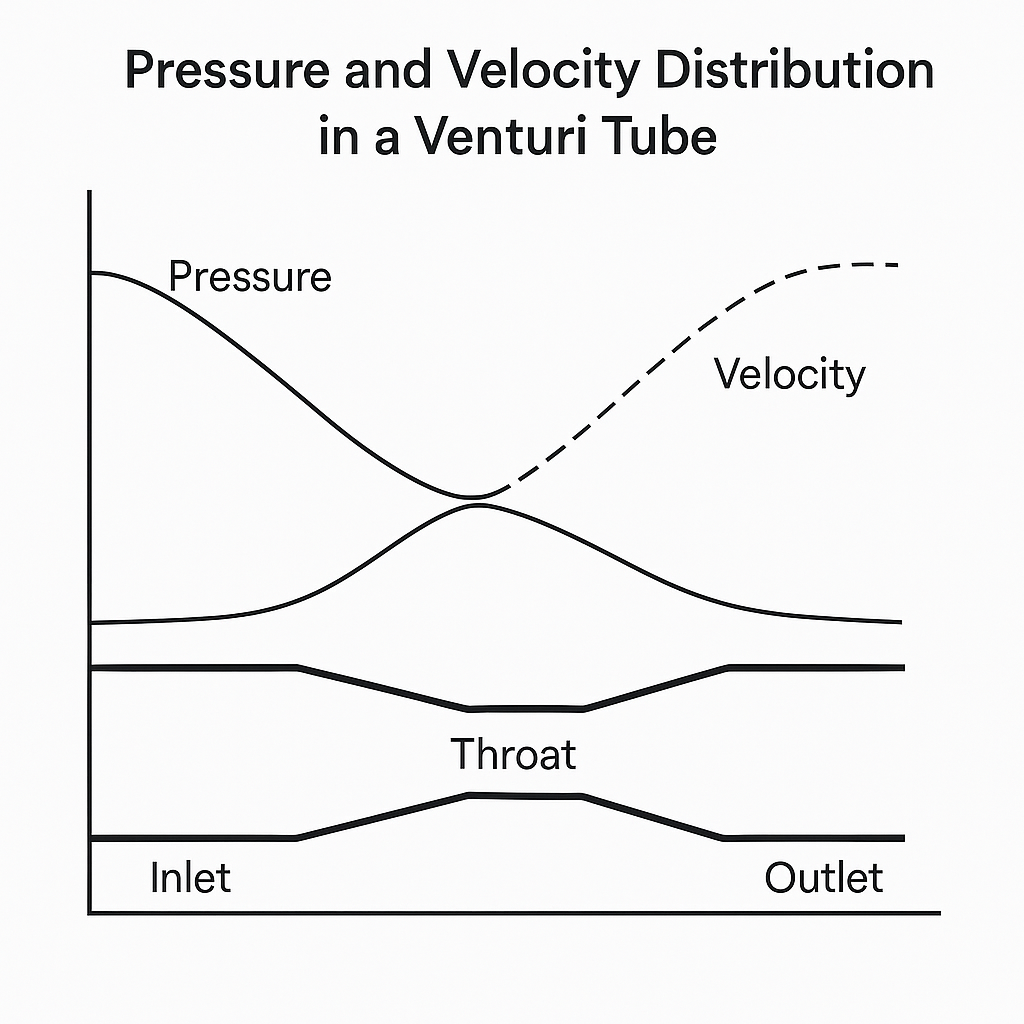
The Venturi flowmeter operates on the Venturi effect, a fluid dynamics phenomenon described by the Bernoulli equation. When a fluid passes through the constricted throat section of a Venturi tube, its velocity increases while the static pressure decreases, maintaining energy conservation.
2. Structure of Venturi Flowmeters
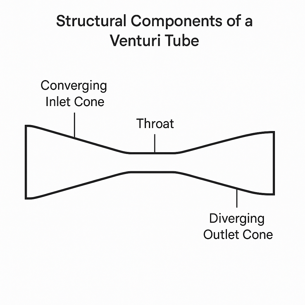
A standard Venturi tube consists of three sections:
Converging inlet cone
Throat section
Diverging outlet cone
Design parameters:
Throat-to-pipe diameter ratio (β = d/D): 0.30 – 0.75
Inlet cone angle (α₁): 21° ± 1°
Outlet cone angle (α₂): 7° – 15°
Throat length: equal to throat diameter
Types: conical type and nozzle type, with both long-form and short-form designs.
3. Advantages and Limitations
Advantages
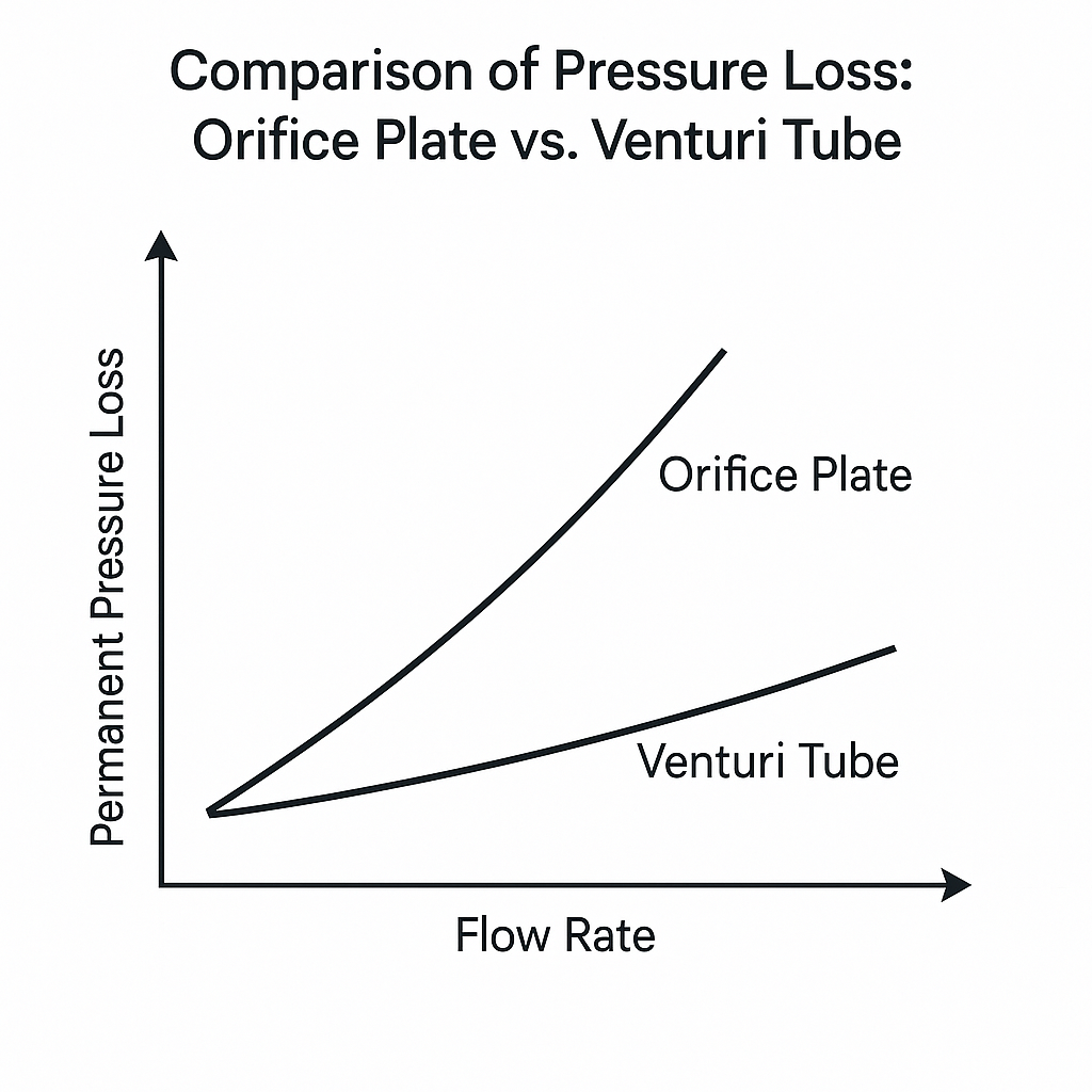
Low permanent pressure loss (~150 Pa).
Large differential pressure, wide measuring range.
Stable performance and smooth ΔP curve.
Applicable to gases, flue gases, and dust-laden streams (e.g., blast furnace gas) without clogging.
Economic considerations: Cost of fabrication, transport, and installation rises sharply.
Reynolds number effects: At low velocities, turbulence is insufficient for reliable measurement.
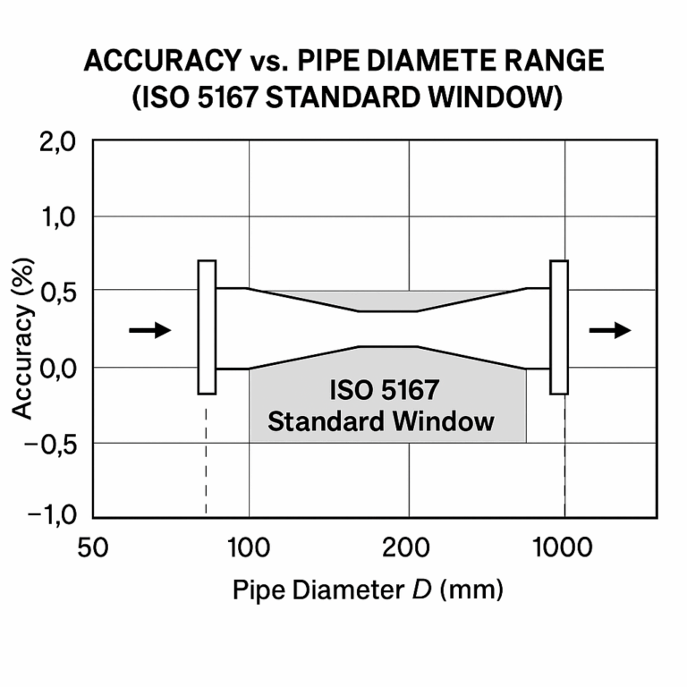
6. Minimum Diameter and β Ratio
Minimum standardized pipe size: 50 mm (2″)
Acceptable β ratio: 0.30 – 0.75
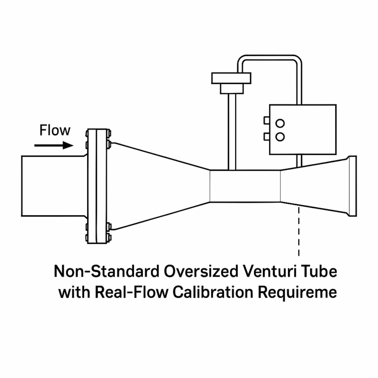
7. Handling Oversized Applications (D >1200 mm)
If the pipeline diameter exceeds 1200 mm:
Non-standard custom fabrication is required.
Mandatory real-flow calibration at a certified flow standard facility (typically water flow rigs).
Calibration provides the actual discharge coefficient, as standard data cannot be applied.
Cost and complexity are high, and accuracy cannot be guaranteed to ISO standards.
8. Conclusion
The standard Venturi flowmeter is reliable and widely used for large-diameter, low-velocity gas and air measurement in industries such as steel, power, and petrochemicals. However:
The ISO/ASME diameter limit (≤1200 mm) must be strictly followed.
For D >1200 mm, only non-standard, custom-built solutions with real-flow calibration can ensure acceptable accuracy.
In many ultra-large-diameter cases, alternative technologies (e.g., insertion-type meters, ultrasonic, or averaging Pitot tubes) may provide a more practical solution.