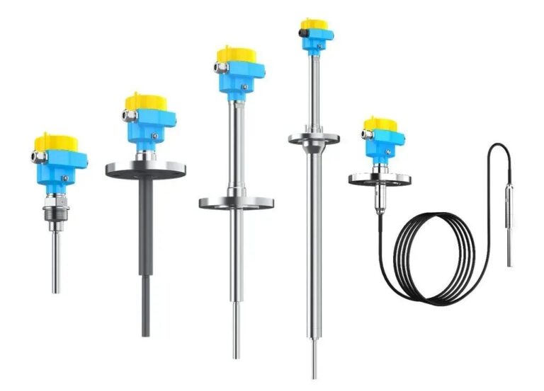
Level instruments are among the most fundamental and critical process control devices in the process industry. They act as the “eyes of the tank,” continuously monitoring level changes in storage tanks, towers, and pipelines.
However, field engineers often encounter a common issue during inspections:
“The tank is clearly empty, but the level gauge does not read zero!”
This is a typical zero drift phenomenon. Although the drift seems minor, it can lead to operational errors, process instability, alarm failure, and even safety incidents. This article analyzes the causes, risks, and countermeasures of zero drift, supported by real-world cases and future trends, to help engineers and managers build a systematic understanding.
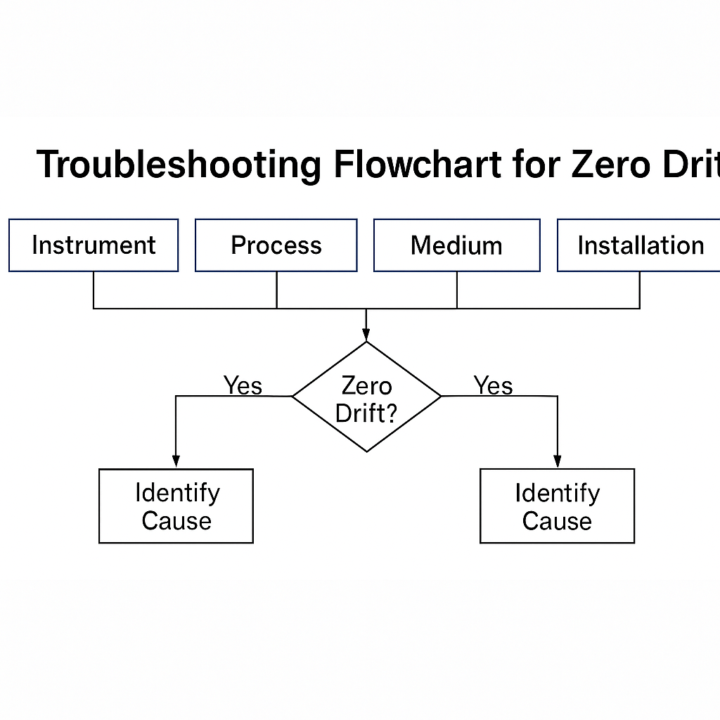
1. Multi-Dimensional Causes of Zero Drift
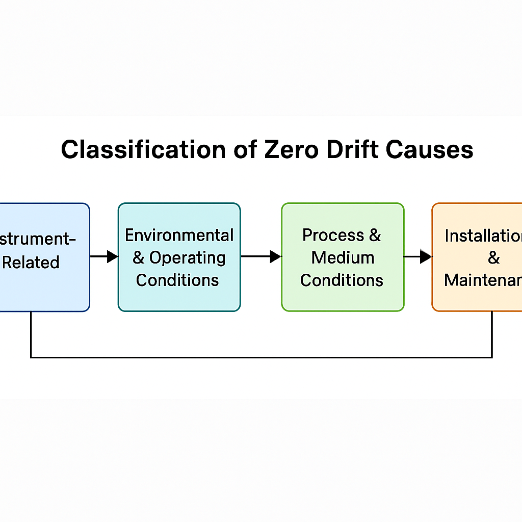
From the surface, zero drift appears as “incorrect readings,” but in essence, it is a baseline shift of the measurement chain. Contributing factors can be grouped into four main categories:
1.1 Instrument-Related Factors
Sensor aging: Diaphragms in DP transmitters, electrodes in capacitive meters, and strain gauges can degrade under long-term high-temperature or high-pressure conditions.
Electronic component drift: Operational amplifiers, resistors, and capacitors gradually deviate due to time or temperature effects.
Fill fluid and sealing: In remote diaphragm transmitters, fill fluid evaporation or leakage in capillaries can cause continuous drift.
1.2 Environmental & Operating Conditions
Temperature stress: Expansion of capillaries or sensing elements shifts the zero point.
Mechanical stress & vibration: Tank wall stress transfer or long-term vibration loosens supports.
Electromagnetic interference: Signals can be distorted by motors, VFDs, or high-frequency wireless sources.
1.3 Process & Medium Conditions
Medium property variation: Capacitive meters depend on dielectric constant; changes in temperature, concentration, or composition cause drift.
Deposition and blockage: Scaling in impulse lines or flanges leads to uneven pressure.
Gas bubbles and vapor: Adhered bubbles or vapor pockets on diaphragms or radar antennas create “false levels.”
1.4 Installation & Maintenance Factors
Improper impulse line slope, poor grounding, or incorrect mounting angles.
Inaccurate calibration due to unstable temperature or mismatched conditions.
Lack of routine maintenance, such as impulse line purging or cable inspections.
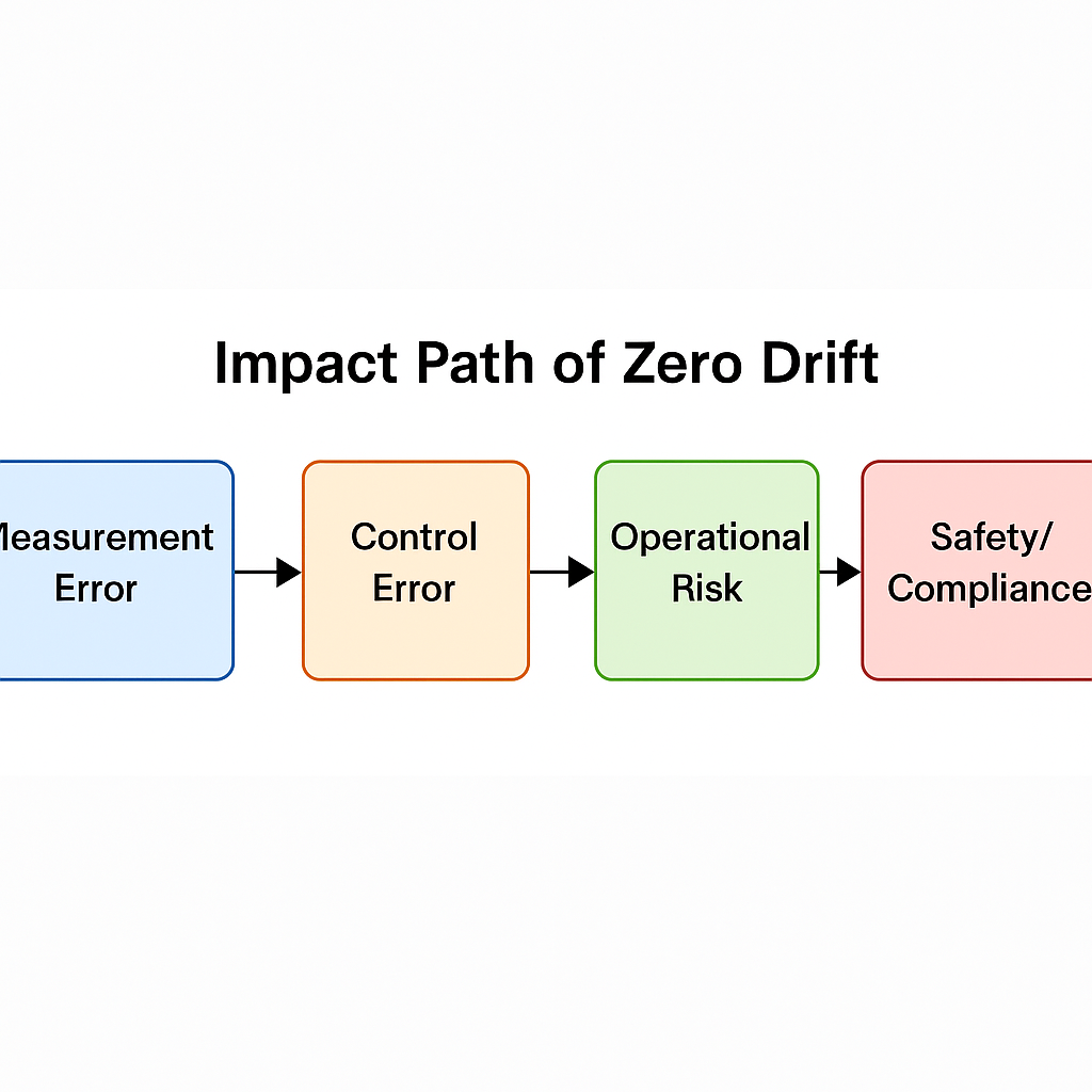
2. Risks and Consequences of Zero Drift
Zero drift is often underestimated, but its consequences are significant:
Process control deviation:
High readings may cause premature pump shutdown; low readings may cause cavitation or dry running.Energy and production loss:
Tower levels directly affect separation efficiency and energy consumption.Safety risks:
False alarms may lead to tank overflow, dry heating, or other incidents.Compliance and management issues:
For oil or chemical storage tanks, inaccurate readings can trigger inventory errors or regulatory violations.
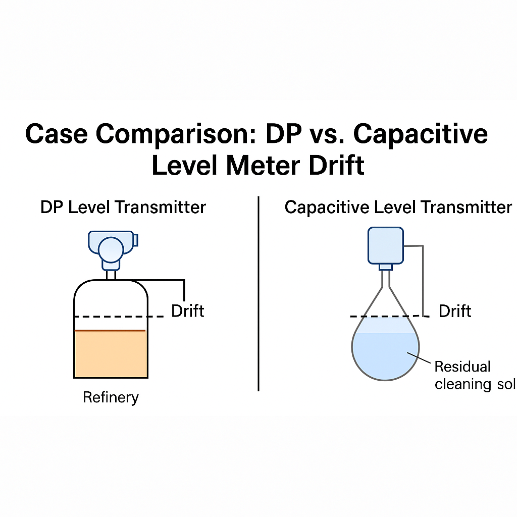
3. Typical Case Studies
Case 1 — Refinery DP Level Transmitter Drift
At a refinery, a bottom DP transmitter on an atmospheric tower experienced a 15% zero drift due to summer heat causing fill fluid evaporation in the capillary. The misjudged tank level led to operational mistakes.
Lesson learned: In high-temperature environments, non-contact radar or remote diaphragm designs should be prioritized.
Case 2 — Food Plant Capacitive Level Transmitter Drift
After CIP cleaning, a dairy plant found abnormal level baselines because residual cleaning solution altered the dielectric constant.
Lesson learned: For frequent cleaning processes, use guided-wave radar or other technologies not dependent on dielectric properties.
4. Preventive Measures and Solutions
4.1 Engineering Selection
High-temperature/high-pressure: Prefer remote diaphragm or radar level meters.
Scaling-prone media: Choose non-contact radar or ultrasonic meters.
4.2 Installation Optimization
Ensure impulse lines are free of gas or liquid blockage.
Maintain good grounding to minimize EMI.
4.3 Operation & Management
Regular zero-point verification under empty-tank or reference conditions.
Apply temperature compensation or software filtering where possible.
4.4 Intelligent Maintenance
Use transmitters with online diagnostics to identify zero drift.
Build historical databases to analyze long-term drift trends and issue early warnings.
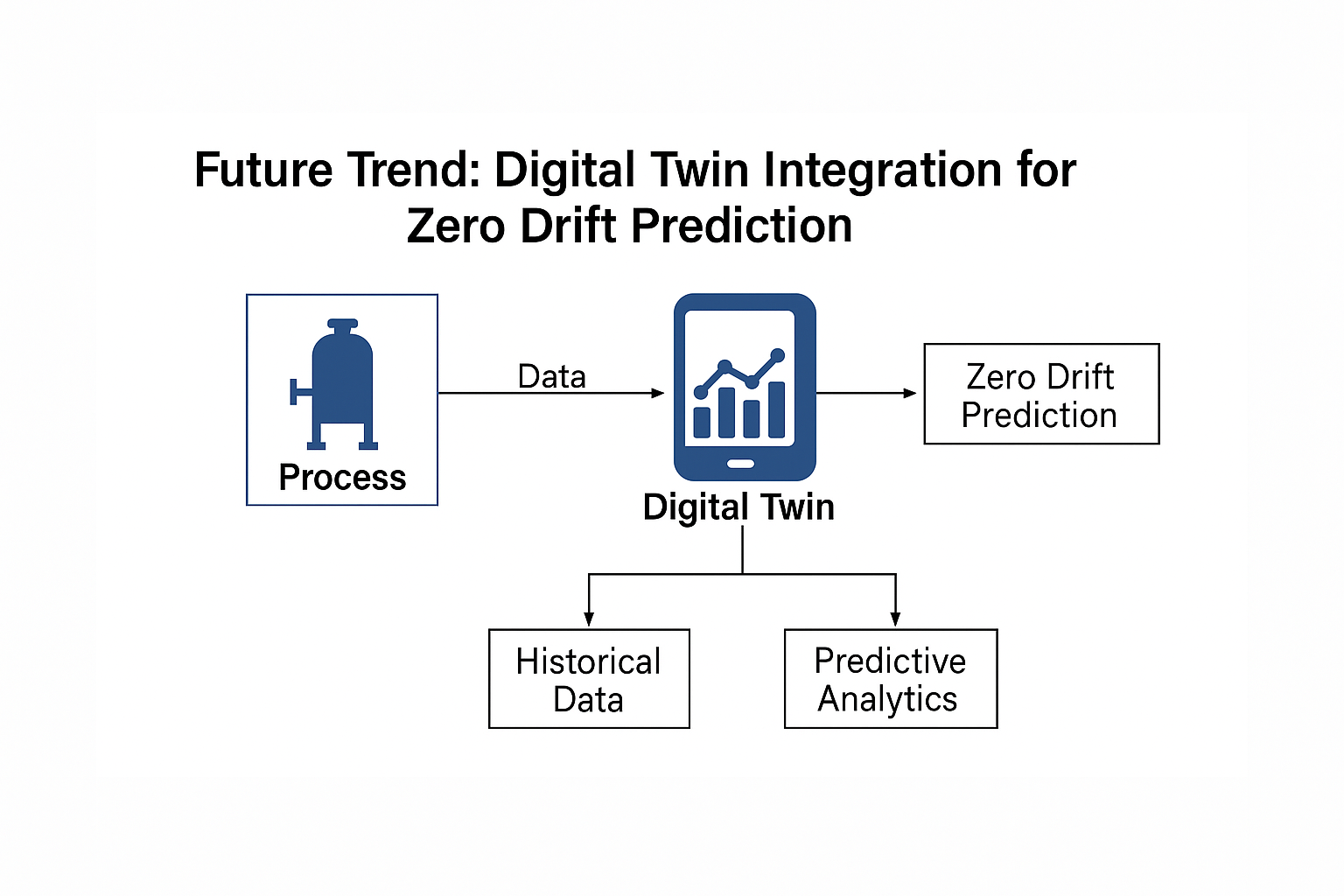
5. From Reactive Calibration to Proactive Diagnostics
With the advancement of Industry 4.0 and smart manufacturing, level measurement is evolving:
Self-diagnosis & auto-calibration:
Modern transmitters integrate temperature compensation and self-learning algorithms to correct baseline shifts.Digital twin & data analytics:
Historical drift data enables predictive models for early anomaly detection.Maintenance-free designs:
FMCW radar and fiber-optic level meters are gaining popularity, reducing mechanical stress and fouling issues.
6. Conclusion
Zero drift in level instruments is not a minor nuisance, but a life-cycle challenge spanning design, selection, installation, operation, and maintenance.
For field engineers, quick troubleshooting and correction are essential.
For management, drift should be treated as a hidden cost in asset and lifecycle management.
Looking forward, with the widespread adoption of smart instruments and data-driven analytics, zero drift will evolve from a hard-to-trace “field headache” into a predictable, manageable, and optimizable issue.